
Control method for processing five-rod five-ring parallel kinematic machine tool

A control method and motion control card technology, applied in the direction of digital control, electrical program control, etc., can solve problems such as ineffectiveness, and achieve the effect of reducing errors, simplifying the operation process, and solving the corresponding speed

Inactive Publication Date: 2009-11-25
TONGJI UNIV
View PDF0 Cites 4 Cited by
  • Summary
  • Abstract
  • Description
  • Claims
  • Application Information

AI Technical Summary

Problems solved by technology

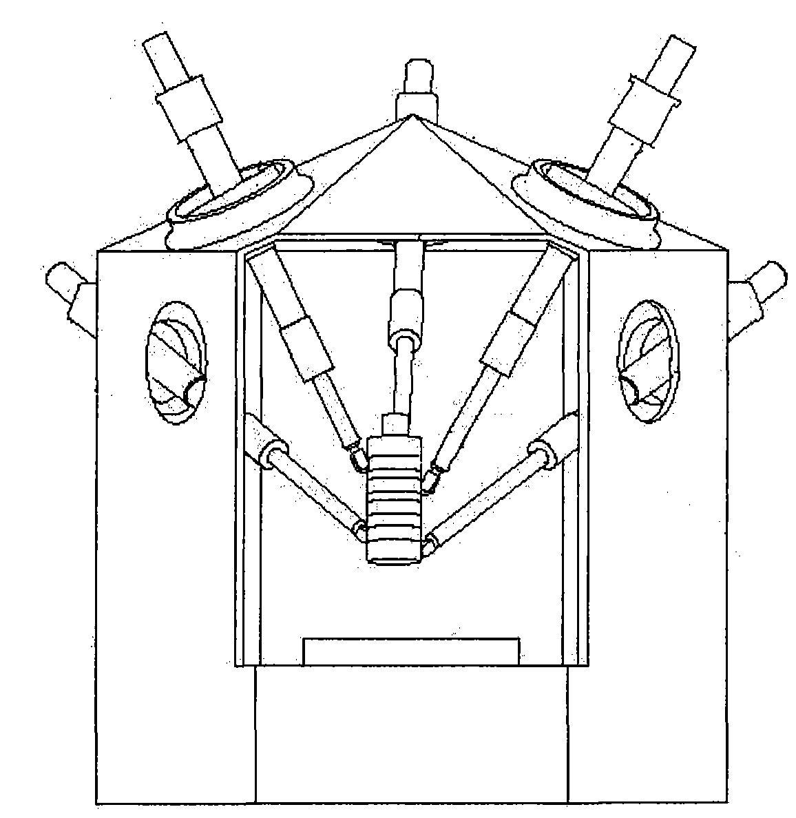
In the past parallel machine tools, whether it is the traditional Stewart six-bar mechanism or the later developed three-bar mechanism in the hybrid machine tool, the hinge points of the bars and the moving platform are always distributed on the second floor plane, while the five-bar five-bar mechanism of the present invention The configuration of the circular parallel kinematic machine tool is five levels controlled by five rods, the centers of the five control surfaces are on the same line, and five swivel rings are used on the moving platform (spindle) to replace the fixedly installed constraint hinges. The position of the constraint hinges is determined by the traditional Known (fixed) becomes unknown (instantaneous rotation), so its kinematic solution is difficult to work with conventional algorithms

Method used


Image

  • Control method for processing five-rod five-ring parallel kinematic machine tool
  • Control method for processing five-rod five-ring parallel kinematic machine tool
  • Control method for processing five-rod five-ring parallel kinematic machine tool

Examples


Embodiment Construction

[0045] Please refer to the accompanying drawings for a further description of the present invention.

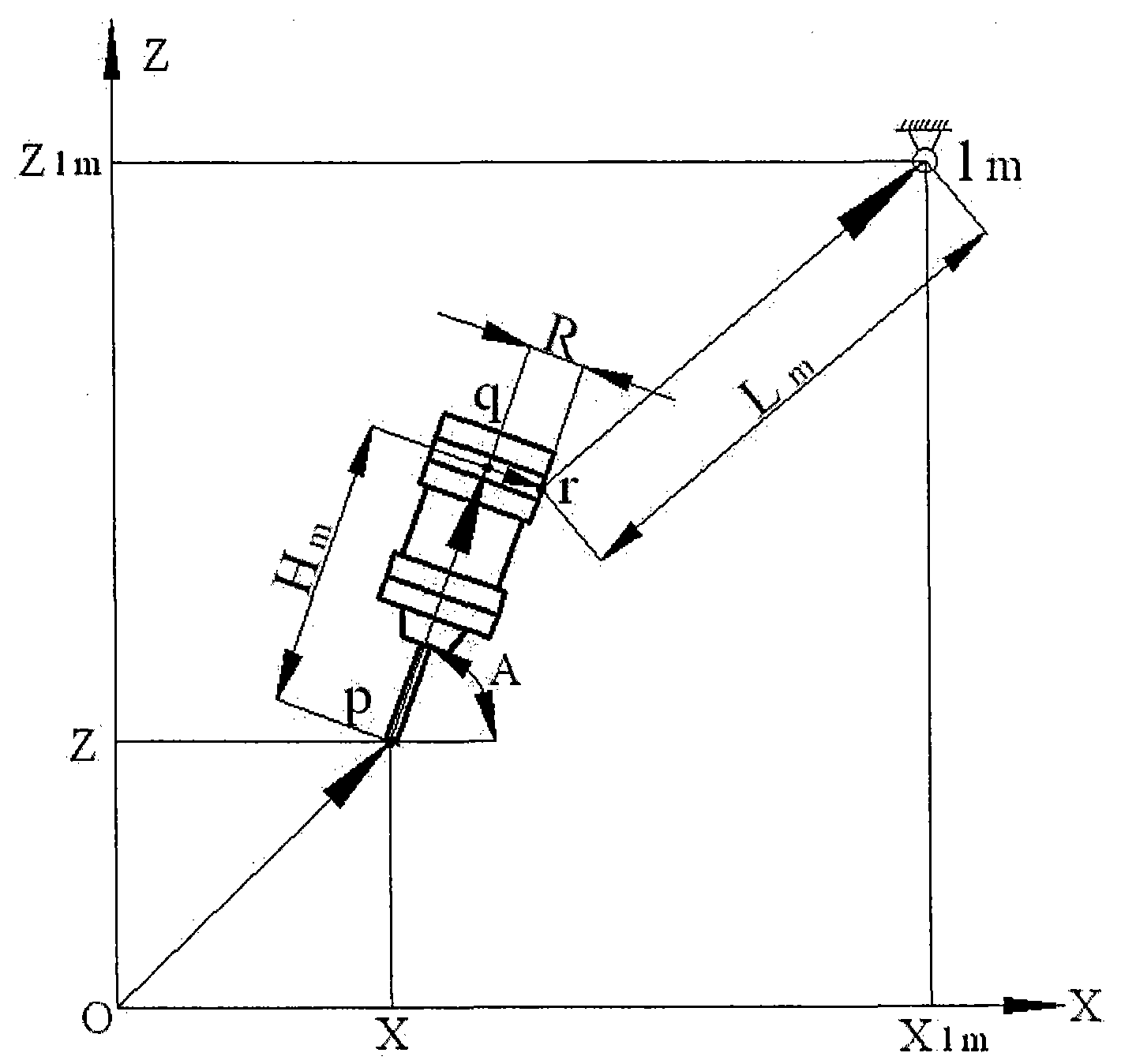
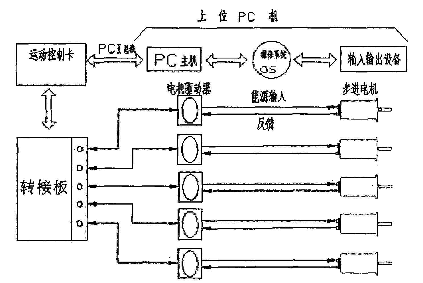
[0046] Such as image 3 As shown, the present invention provides a five-bar five-ring parallel kinematic machine tool processing control method. The numerical control system of the five-bar five-ring parallel kinematic machine tool is bidirectionally connected with the upper PC and the servo control system by a motion control card. The control method includes the following steps: (1) Establishing a control model, which forms a one-to-one functional relationship between the structural geometric parameters of the five-bar five-ring parallel machine tool, the size of the tool, and the mathematical model of the surface of the workpiece to be machined, such as figure 2 As shown, the rod length function is obtained;

[0047] combine Figure 5A , Figure 5B and Figure 5C Introducing the specific implementation of the present invention, the structural dimensions include the rad...


PUM


Abstract

The invention provides a control method for processing five-rod five-ring parallel kinematic machine tool, and the numerical control system of the five-rod five-ring parallel kinematic machine tool has a two-way linkage with a upper PC and a servo control system by a motion control card, and the control method includes (1) establishing a control model, and forming a functional relation in one-to-one correspondence by the control model for the five-rod five-ring parallel kinematic machine tool structure geometric parameter, the knife dimension and the surface of workpiece to be processed, and obtaining rod length function; (2) writing five-rod length function into the motion control card by the upper machine; (2) setting rotative velocity of electronic cam wheel in the motion control card according to the cutting feed speed; (4) outputting the control signal to the servo control system by the motion control card, and controlling machine tool for carrying out processing. The invention has the advantages that the control model translates the solving of staggered vector space into the solving of planar vector, which simplifies the arithmetic process, improves the interpolation speed for processing; and the function of the electronic cam wheel replaces the function of the cam wheel, which resolves the synchronous of every corresponding interpolation point of five drive rods.

Description

technical field [0001] The invention relates to a control method for machine tool processing, in particular to a control method for five-rod and five-ring parallel kinematic machine tool processing. Background technique [0002] Parallel kinematic machine tools, also known as virtual axis machine tools, have been developed for nearly ten years at home and abroad, and most of the parallel kinematic mechanisms are six-bar and three-bar. It is rare to use a five-bar complete parallel mechanism as a parallel machine tool, and the research object of the present invention is just a five-bar five-ring parallel kinematic machine tool. [0003] The five-bar five-ring parallel mechanism was proposed by Dr. Michael Schwaar of Germany in 2001. Compared with other types of parallel kinematic machine tools, it has its particularity, such as figure 1 shown. In the past parallel machine tools, whether it is the traditional Stewart six-bar mechanism or the later developed three-bar mechani...

Claims


Application Information

Patent Timeline
Patent Type & Authority Applications(China)
IPC IPC(8): G05B19/18
Inventor 谢红高志林
Owner TONGJI UNIV
Learn More