Radio communication method and radio communication device
一种无线通信、通信环境的技术,应用在无线通信、多路复用通信、分集/多天线系统等方向,能够解决功率放大器消耗功率变大、消耗功率变大等问题,达到抑制干扰、提高频率利用效率的效果
- Summary
- Abstract
- Description
- Claims
- Application Information
AI Technical Summary
Problems solved by technology
Method used
Image


Examples
Embodiment approach 1
[0057] figure 2 An example of the transmission flow between the base station and the terminal according to this embodiment is shown. Here, the base station and terminal A and terminal B are in Figure 1A In the relationship shown, terminal A and terminal B through the uplink will figure 2 The signal shown is sent to the base station, which downlinks the figure 2 The signal shown is sent to Terminal A and Terminal B.
[0058] First, terminal A transmits a reference symbol (reference symbol) 101 and a request information symbol 102 . The reference symbol 101 is, for example, a symbol whose signal point configuration on the I-Q plane between transceivers is known. The request information symbol 102 is, for example, a symbol including information on a transmission rate desired by a terminal such as a modulation scheme or a coding rate (MCS, Modulation and Coding Scheme).
[0059] Next, terminal B transmits reference symbol 103 and request information symbol 104 .
[0060] ...
Embodiment approach 2
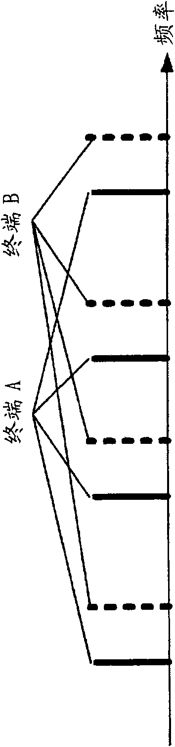
[0119] In this embodiment, in the Distributed SC-FDMA scheme, it is proposed to make the regularity of frequency allocation different for each terminal.
[0120] Before describing the present embodiment, first, the procedure for producing the present embodiment will be described using FIG. 8 . FIG. 8 shows an example of a frequency allocation method of the Distributed SC-FDMA scheme. The feature in FIG. 8 is that frequencies are distributed at intervals of the same N carriers to all terminals A, B, and C. FIG.
[0121] Figure 8A A case where adjacent frequencies are allocated to terminal A, terminal B, and terminal C is shown. At this time, at Figure 8A In , the assigned frequency is different, but since the actual internal frequency source of each terminal A, terminal B, and terminal C is different, there is a high possibility that mutual interference will occur on all the carriers. Therefore, a reduction in reception quality is caused.
[0122] As a method of suppress...
Embodiment approach 3
[0137] In this embodiment, it is proposed to change the carriers allocated to terminals temporally in the Distributed SC-FDMA scheme.
[0138] use Figure 10 and Figure 11 The frequency allocation method of this embodiment will be described. in addition, Figure 10 Indicates the frequency band allocation method of this embodiment, Figure 11 shows its comparative example.
[0139] exist Figure 10 and Figure 11 Among them, the horizontal axis is frequency, and the vertical axis is time. In addition, the carrier of the solid line indicated by reference numeral 901 represents the carrier of the Distributed SC-FDMA system in which the frequency is allocated every N carrier intervals, and the carrier of the dotted line indicated by the reference numeral 902 represents the Distributed SC-FDMA system in which the frequency is allocated every M carrier interval. The carrier of the FDMA method. Wherein, N and M are in the relationship of N≠M. In addition, reference numeral 90...
PUM
 Abstract
Description
Claims
Application Information
 - R&D Engineer
- R&D Manager
- IP Professional
- Industry Leading Data Capabilities
- Powerful AI technology
- Patent DNA Extraction
Browse by: Latest US Patents, China's latest patents, Technical Efficacy Thesaurus, Application Domain, Technology Topic.
© 2024 PatSnap. All rights reserved.Legal|Privacy policy|Modern Slavery Act Transparency Statement|Sitemap