Voltage stabilizer

A voltage stabilizer, stable technology, used in instruments, regulating electrical variables, control/regulating systems, etc., can solve problems such as negative effects of phase margin improvement, poor transient response of voltage stabilizers, etc.

Inactive Publication Date: 2009-11-18
RICOH MICROELECTRONICS CO LTD
View PDF0 Cites 10 Cited by
  • Summary
  • Abstract
  • Description
  • Claims
  • Application Information

AI Technical Summary

Problems solved by technology

But adding a follower stage introduces a new pole which negatively impacts the phase margin improvement
Therefore, a Miller RC compensation device can be added to the above structure to improve the phase margin, but in doing so, the voltage regulator often has the disadvantage of poor transient response due to the influence of capacitance

Method used


Image

  • Voltage stabilizer
  • Voltage stabilizer
  • Voltage stabilizer

Examples


Embodiment Construction

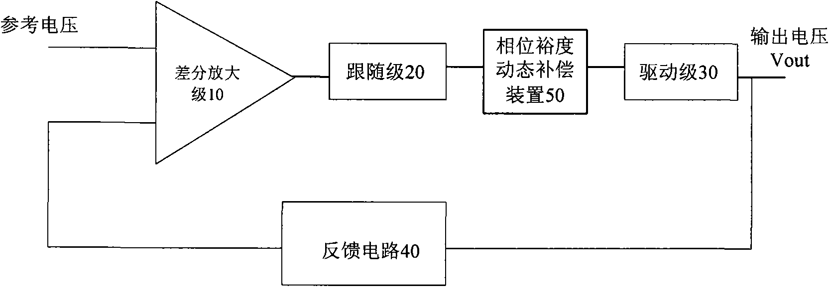
[0017] Usually, the structural block diagram of a voltage regulator that uses the method of adding a follower stage for phase compensation is as follows: figure 1 As shown, it includes a differential amplifier stage 10, a follower stage 20, a driver stage 30 cascaded with each other, and a feedback circuit 40 fed back from the output of the driver stage 30 to the input terminal of the differential amplifier stage. The regulator adjusts the input voltage, and finally the driving stage 30 outputs a stable output voltage. The follower stage is cascaded with the differential amplifier stage 10, which is used to improve the system phase margin of the entire voltage regulator. Wherein, if the output voltage of the driving stage 30 can bypass the feedback circuit 40 and directly feed back to the differential amplifier stage 10 .

[0018] The improvement of the present invention is that a phase margin dynamic compensation device 50 is added after the following stage 20 as a load of t...


PUM


Abstract

The invention provides a voltage regulator which is used for regulating input voltage into stable output voltage and comprises a following stage and a driving stage, wherein the driving stage receivesthe output of the following stage and outputs regulated voltage for load, and a dynamic compensating device of phase margins, which improves the phase margins with the increase of the load current ofthe load is connected between the following stage and the driving stage.

Description

technical field [0001] The invention relates to a voltage regulator, in particular to a low drop-out (Low Drop-out) voltage regulator. Background technique [0002] Almost all electronic circuits require a stable voltage source maintained within certain tolerances to power a specific component for proper operation. This regulated voltage is provided by a voltage regulator. [0003] A common voltage regulator mainly includes: a differential amplifier stage, a driver stage (for example, P-FET, PNP as a driver transistor) and a feedback circuit for feeding back the output voltage to the differential amplifier stage at a certain ratio. In the existing voltage regulator technology, in order to maintain the stability of the output voltage, a follower stage is usually added between the differential amplifier stage and the driver stage, so that the pole introduced by the differential amplifier stage moves to the high frequency direction to improve the phase margin. But adding a fo...

Claims


Application Information

Patent Timeline
Patent Type & Authority Applications(China)
IPC IPC(8): G05F1/56
Inventor 卢凯伊藤弘造
Owner RICOH MICROELECTRONICS CO LTD
Why Eureka
Try Eureka