
Traction sliding hydraulic support system

A hydraulic support and traction technology, which is applied to mine roof support, mining equipment, earthwork drilling and other directions, can solve problems such as damage to the connecting mechanism, achieve uniform distribution of support force, compact structure, and improve safety and reliability.

Inactive Publication Date: 2009-11-04
BEIJING CHENGTIAN HENGYE COAL MINE EQUIP CO LTD
View PDF0 Cites 0 Cited by
  • Summary
  • Abstract
  • Description
  • Claims
  • Application Information

AI Technical Summary

Problems solved by technology

[0002] Coal mine support equipment is an important facility to ensure the safety of coal mine workers. The existing suspension or sliding hydraulic support is a support equipment that moves forward in a suspended state after the support is unloaded and lifted. The support that the support bears is perpendicular to The gravity of the top beam and the tension parallel to the top beam are transmitted to the adjacent brackets through the connection mechanism between the brackets, which makes the connection between the brackets bear a large force, especially for all brackets connected through the connection mechanism The combined sliding hydraulic support, the internal stress generated between the supports will be superimposed on the connecting mechanism, causing frequent damage to the connecting mechanism

Method used


Image

  • Traction sliding hydraulic support system
  • Traction sliding hydraulic support system
  • Traction sliding hydraulic support system

Examples


Embodiment Construction

[0016] The present invention will be further described in detail below in conjunction with the accompanying drawings and specific embodiments.

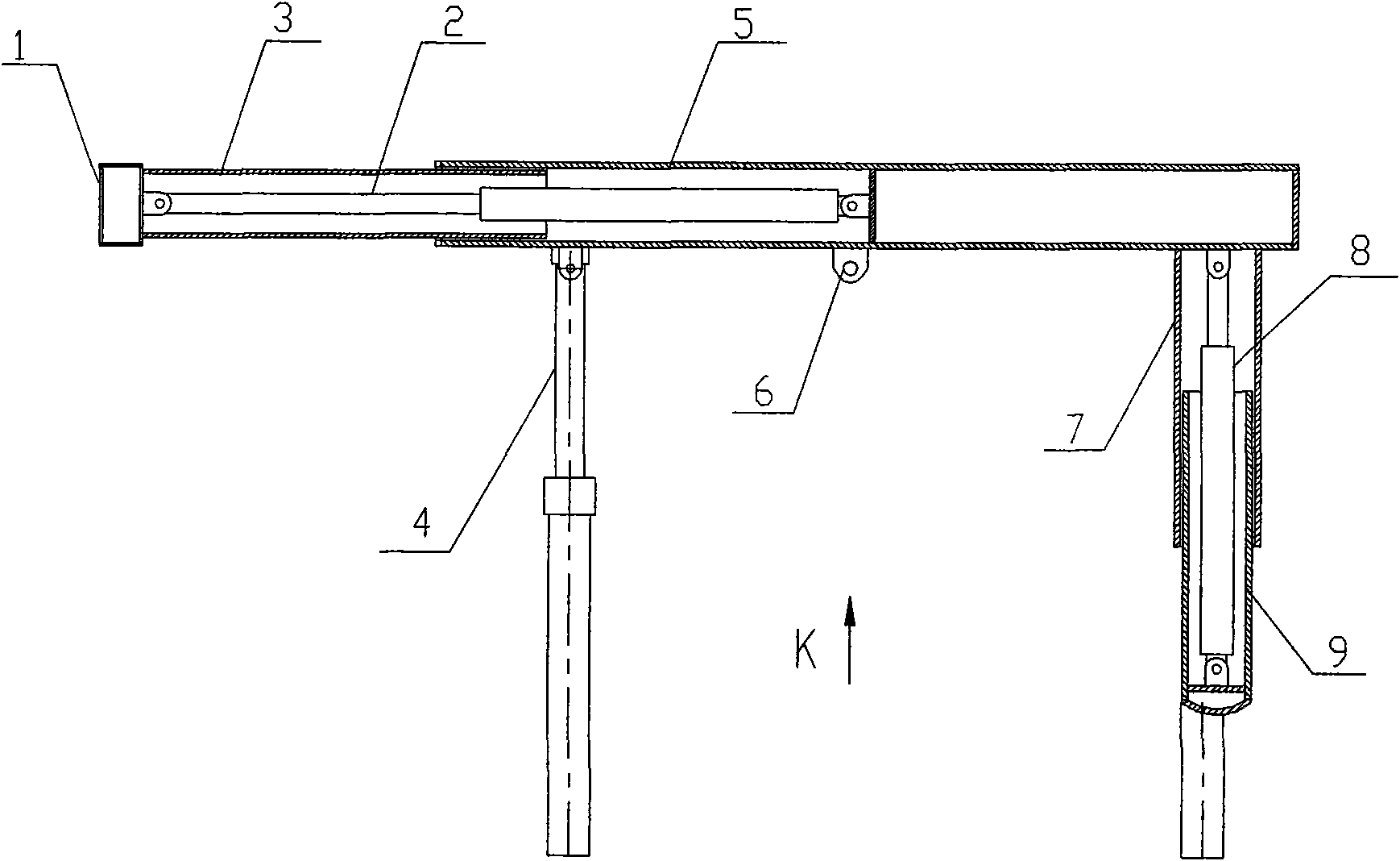
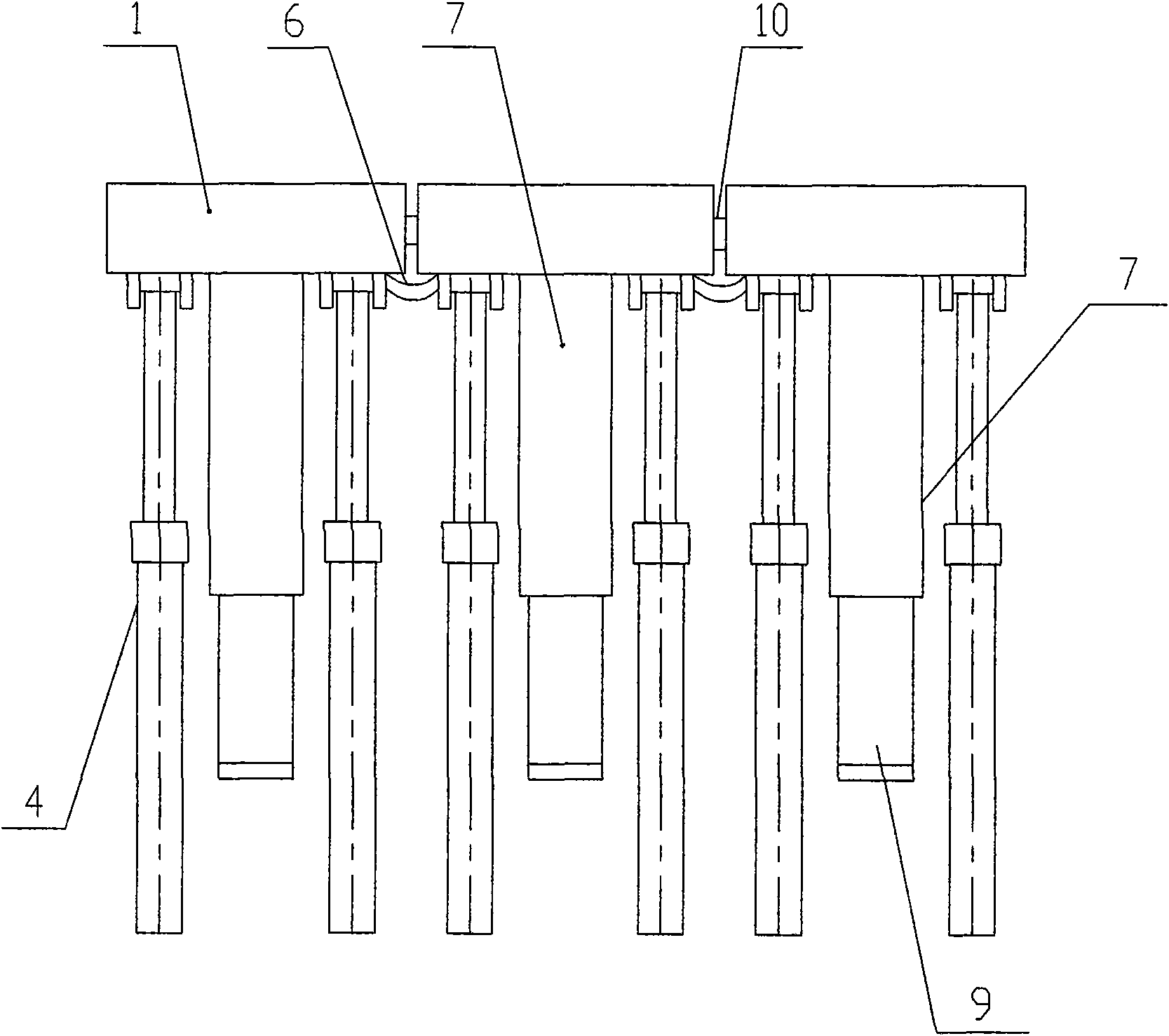
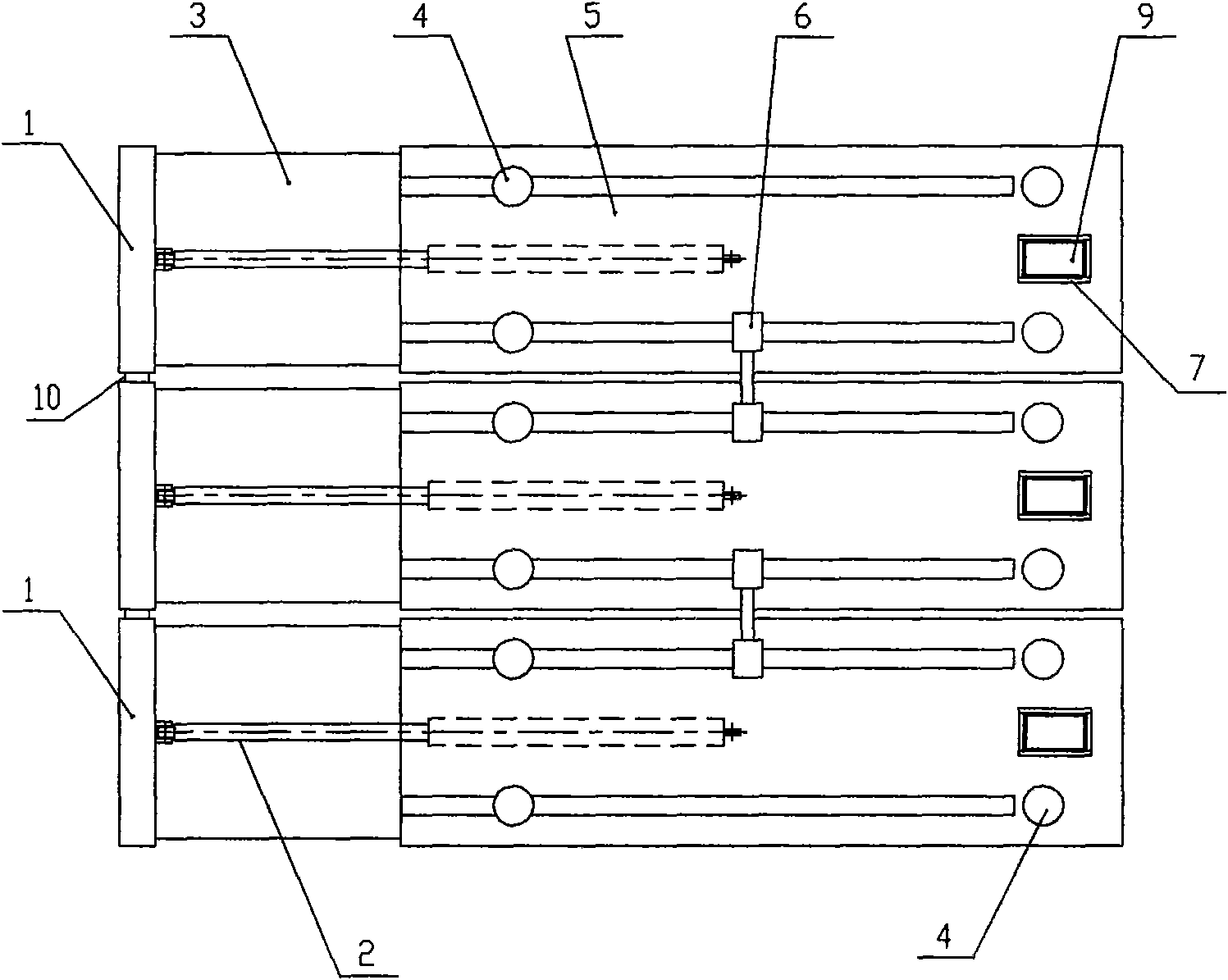
[0017] combine figure 1 , figure 2 with image 3 As shown, the traction sliding hydraulic support system is composed of three traction sliding hydraulic support connections. The traction sliding hydraulic support includes a beam 1, a push jack 2, a guide device 3, a hydraulic prop 4, a top beam 5 and a support system. One end of the guide device 5 is fixed to the beam 1 , and the other end is slidably connected to the top beam 5 . One end of the push jack 2 is connected to the beam 1, and the other end is connected to the top beam 5. When the push jack 2 stretches, the top beam 5 can approach or move away from the cross beam 1 within the range limited by the guide device 5.

[0018] The hydraulic prop 4 is vertically installed on the bottom surface of the top beam 5, and the number of installations is four. It mainly plays the ro...


PUM


Abstract

The invention relates to a traction sliding hydraulic support system which is formed by combining more than two traction sliding hydraulic supports. Each traction sliding hydraulic support comprises a cross beam, a top beam, a hydraulic jack, a hydraulic prop, a guide device and a support system. The cross beam is arranged at the front end of the top beam; one end of the guide device is fixed at the cross beam, the other end is connected in the top beam in a sliding manner; one end of the hydraulic jack is connected with the cross beam, the other end is connected with the top beam, the extension and the contraction of the hydraulic jack can drive the top beam to be near to or far from the cross beam within the range of the guide device; and the telescopic hydraulic prop and the support system are arranged on the bottom surface of the top beam. The cross beams of the adjacent supports form an integrated rigid beam through a connecting device, and the top beams of the adjacent supports are mutually connected by a sliding block. When the traction sliding hydraulic support system moves the supports, the adjacent supports are taken as support points for each other for respective movement, the support system simultaneously plays the support role for the supports, the support force is evenly distributed, the structure is compact and reasonable, and the safety and the reliability of the working environment of coal mining workers are improved.

Description

technical field [0001] The invention relates to a coal mine hydraulic support, in particular to a traction type sliding hydraulic support system. Background technique [0002] Coal mine support equipment is an important facility to ensure the safety of coal mine workers. The existing suspension or sliding hydraulic support is a support equipment that moves forward in a suspended state after the support is unloaded and lifted. The support that the support bears is perpendicular to The gravity of the top beam and the tension parallel to the top beam are transmitted to the adjacent brackets through the connection mechanism between the brackets, which makes the connection between the brackets bear a large force, especially for all brackets connected through the connection mechanism The combined sliding hydraulic support, the internal stress generated between the supports will be superimposed on the connecting mechanism, causing frequent damage to the connecting mechanism. Cont...

Claims


Application Information

Patent Timeline
IPC IPC(8): E21D23/04E21D23/16
Inventor 王洪英徐兴强毛君
Owner BEIJING CHENGTIAN HENGYE COAL MINE EQUIP CO LTD
Learn More