
Tensioner assembly comprising a displaceable tensioning rail

A technology for tensioning slide rails and tensioners, which is applied to transmission devices, belts/chains/gears, mechanical equipment, etc., to achieve the effect of saving construction space and increasing construction space

Inactive Publication Date: 2009-10-28
IWIS MOTORSYSTEME GMBH & CO KG
View PDF3 Cites 8 Cited by
  • Summary
  • Abstract
  • Description
  • Claims
  • Application Information

AI Technical Summary

Problems solved by technology

The disadvantage is that, when used in other engines, the tensioner assembly must be adapted to the respective requirements

Method used


Image

  • Tensioner assembly comprising a displaceable tensioning rail
  • Tensioner assembly comprising a displaceable tensioning rail
  • Tensioner assembly comprising a displaceable tensioning rail

Examples


Embodiment Construction

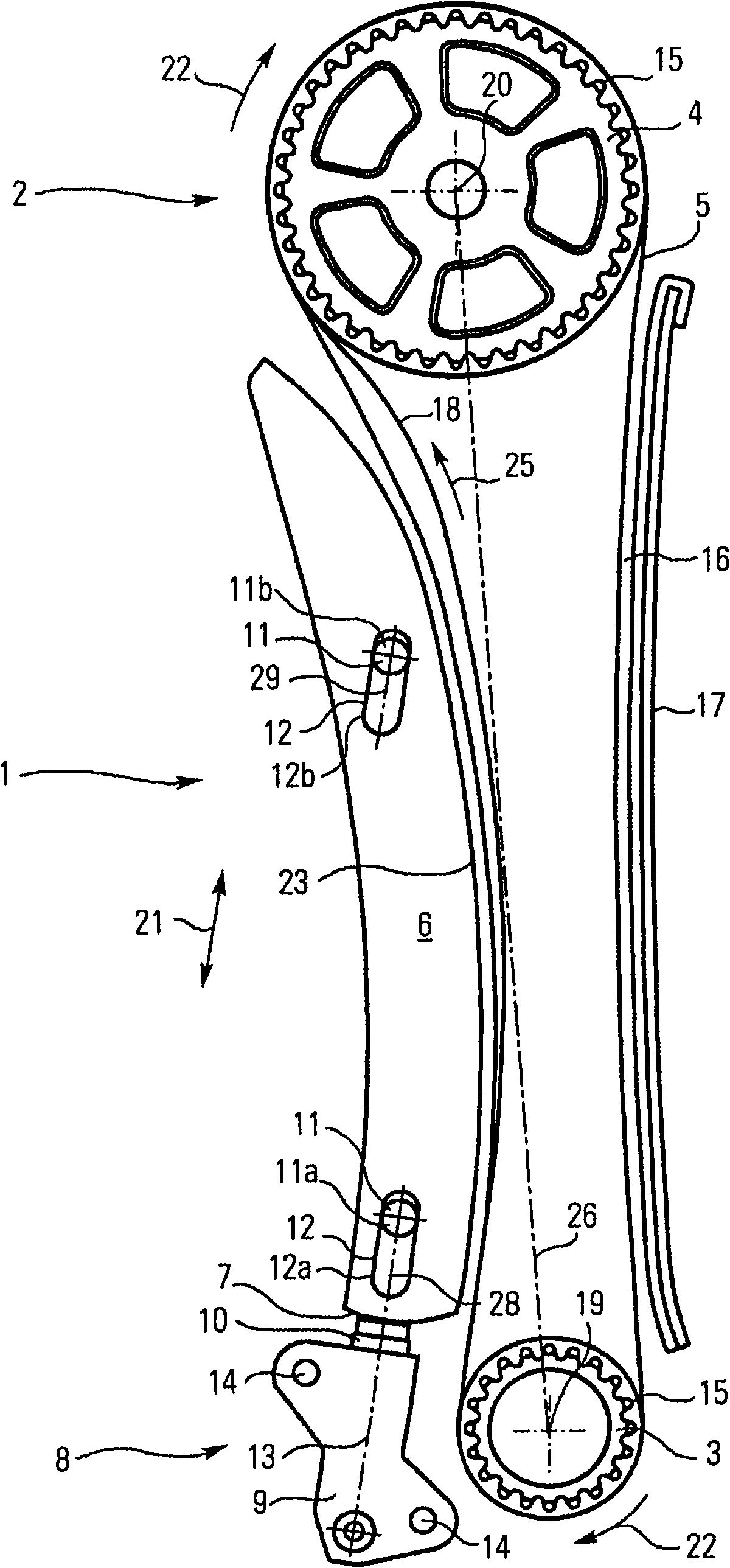
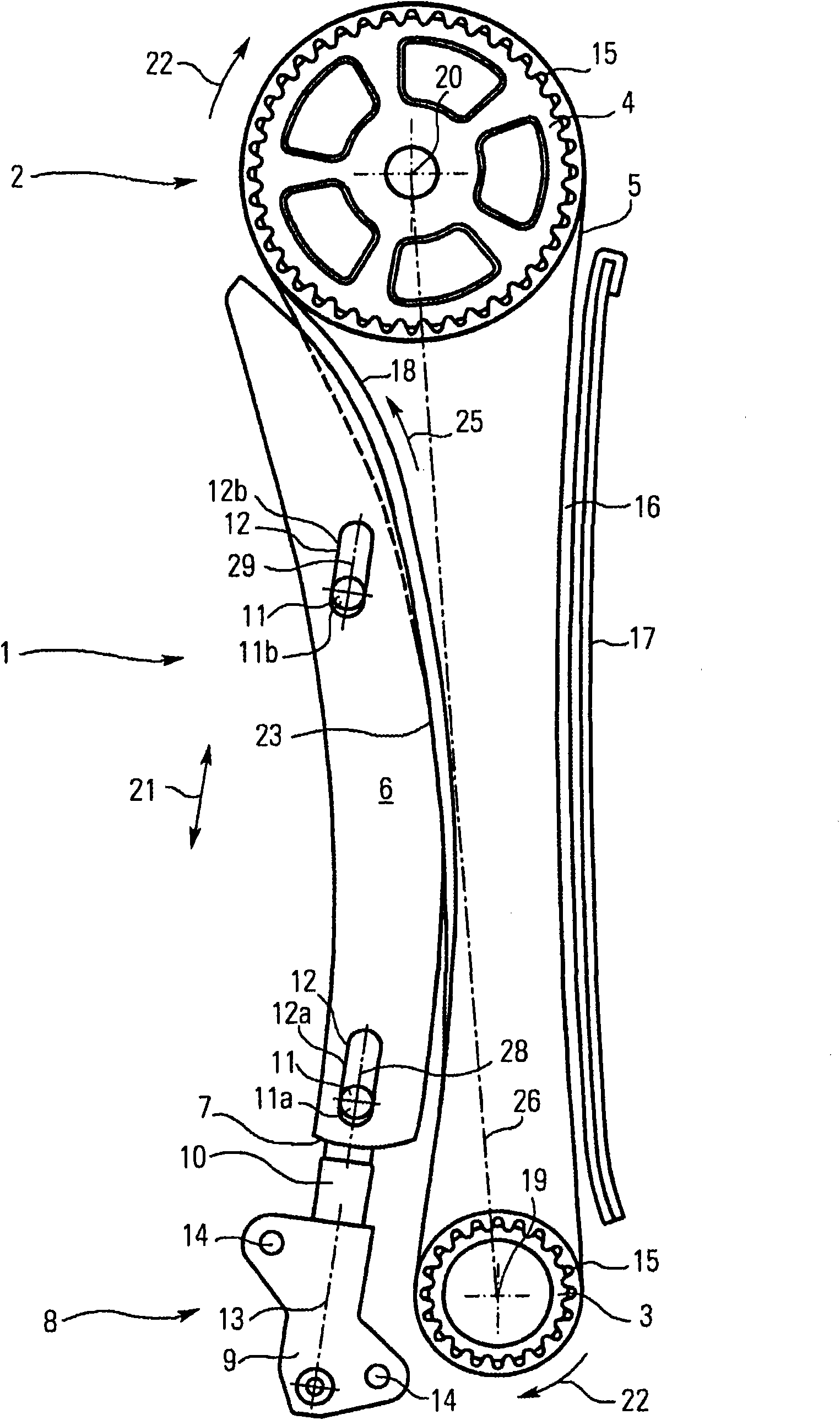
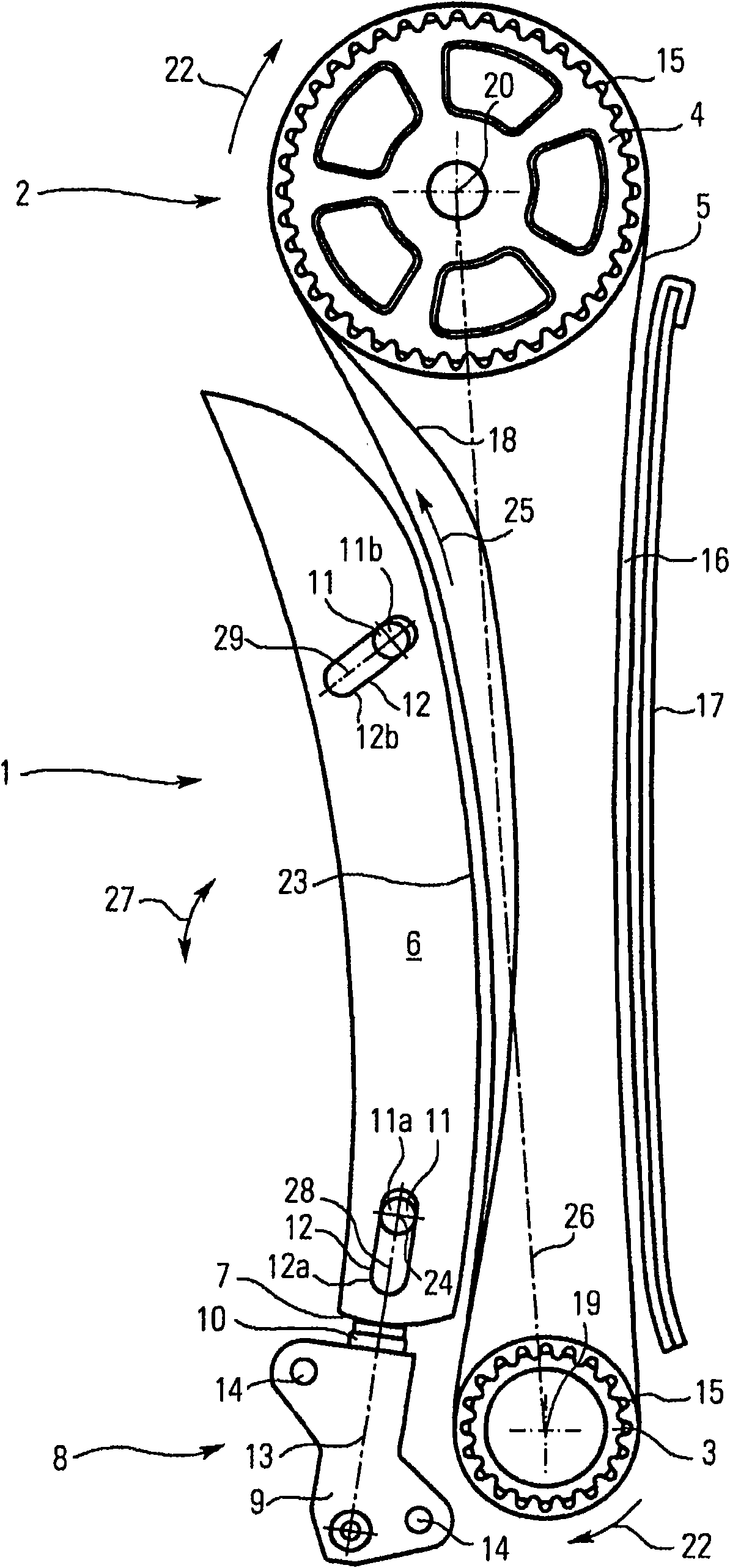
[0026] The tensioner assembly basically consists of a tensioning rail 6 with a curved running surface 23 and a tensioning device 8 . The tensioning device 8 is arranged to extend the tensioning slide 6 . The tensioning piston 10 of the tensioning device 8 is in contact with the tensioning slide 6 via the operating surface 7 . In the illustrated embodiment, the tensioning device 8 comprises a housing 9 in which a tensioning piston 10 is movably mounted. The housing 9 may be fixed to the crankcase or to the engine compartment via the fixing points 14 or in any other way.

[0027] In addition to the chain tensioner illustrated in the figures with a tensioning piston, other tensioners, such as leaf springs or torsion springs, respectively, can also be used.

[0028] The tensioning slide 6 comprises two guide contours 12 through which slide guides 11 designed as bolts 11a, 11b extend. In the illustrated embodiment, the guide profile 12 is formed as mutually spaced oblong holes 1...


PUM


Abstract

The invention relates to a tensioner assembly for a traction medium drive, specifically a chain drive, with at least two traction medium wheels and a flexible traction medium, comprising a tensioning rail which can be pressed against the traction medium by means of a tensioning device, wherein the tensioning rail is applied against at least one sliding guide and can be displaced along the at leastone sliding guide by means of the tensioning device.

Description

technical field [0001] The present invention relates to a tensioner assembly for a traction medium transmission, especially a chain transmission, with at least two traction medium wheels and a flexible traction medium, the tensioner assembly comprising The device is pressed against the tensioning slides of the traction medium. Background technique [0002] Tensioner assemblies of this type are used, for example, to tension valve trains or transmissions of auxiliary components of internal combustion engines. This tensioner assembly can be used for both chain and belt drives. Bothersome vibrations and premature wear are thereby mitigated. [0003] A common tensioner assembly is known from DE 29719734 U1. A tensioning slide for applying tension to the chain drive is rotatably fixed at one end. The fixed point defines a pivot axis about which the tensioning slide moves when a load is introduced by the chain tensioner mounted on the opposite end. The tensioning piston of the...

Claims


Application Information

Patent Timeline
IPC IPC(8): F16H7/08
CPCF16H7/08F16H2007/0872F16H2007/0891F16H2007/0893
Inventor C·鲍尔H·赫格林
Owner IWIS MOTORSYSTEME GMBH & CO KG
Learn More