
Chimney hydraulic mould lifting device

A technology of hydraulic lifting and chimney, which is applied in the fields of formwork/formwork/work frame, on-site preparation of building components, construction, etc., which can solve the problem of poor synchronization of electric sliding form lifting, fragile lead screw and nut, and pulling on the surface of the cylinder. It can overcome problems such as cracking, and achieve the effect of overcoming poor synchronization of lifting, safe installation and dismantling process, and stable construction system.

Active Publication Date: 2011-04-06
POWERCHINA SEPCO1 ELECTRIC POWER CONSTR CO LTD
View PDF0 Cites 0 Cited by
  • Summary
  • Abstract
  • Description
  • Claims
  • Application Information

AI Technical Summary

Problems solved by technology

However, the sliding form construction method has four common quality problems, namely, center drift, cylinder torsion, indentation, and surface cracking of the cylinder. The construction of the derrick requires multiple cable wind ropes, which occupies a large area, high labor intensity, and low efficiency. Disadvantages of high loss; poor synchronization of electric sliding mode lifting, lead screw and nut are fragile and inconvenient to check, poor safety

Method used


Image

  • Chimney hydraulic mould lifting device
  • Chimney hydraulic mould lifting device
  • Chimney hydraulic mould lifting device

Examples


Embodiment Construction

[0027] The present invention will be further described below in conjunction with the accompanying drawings and embodiments.

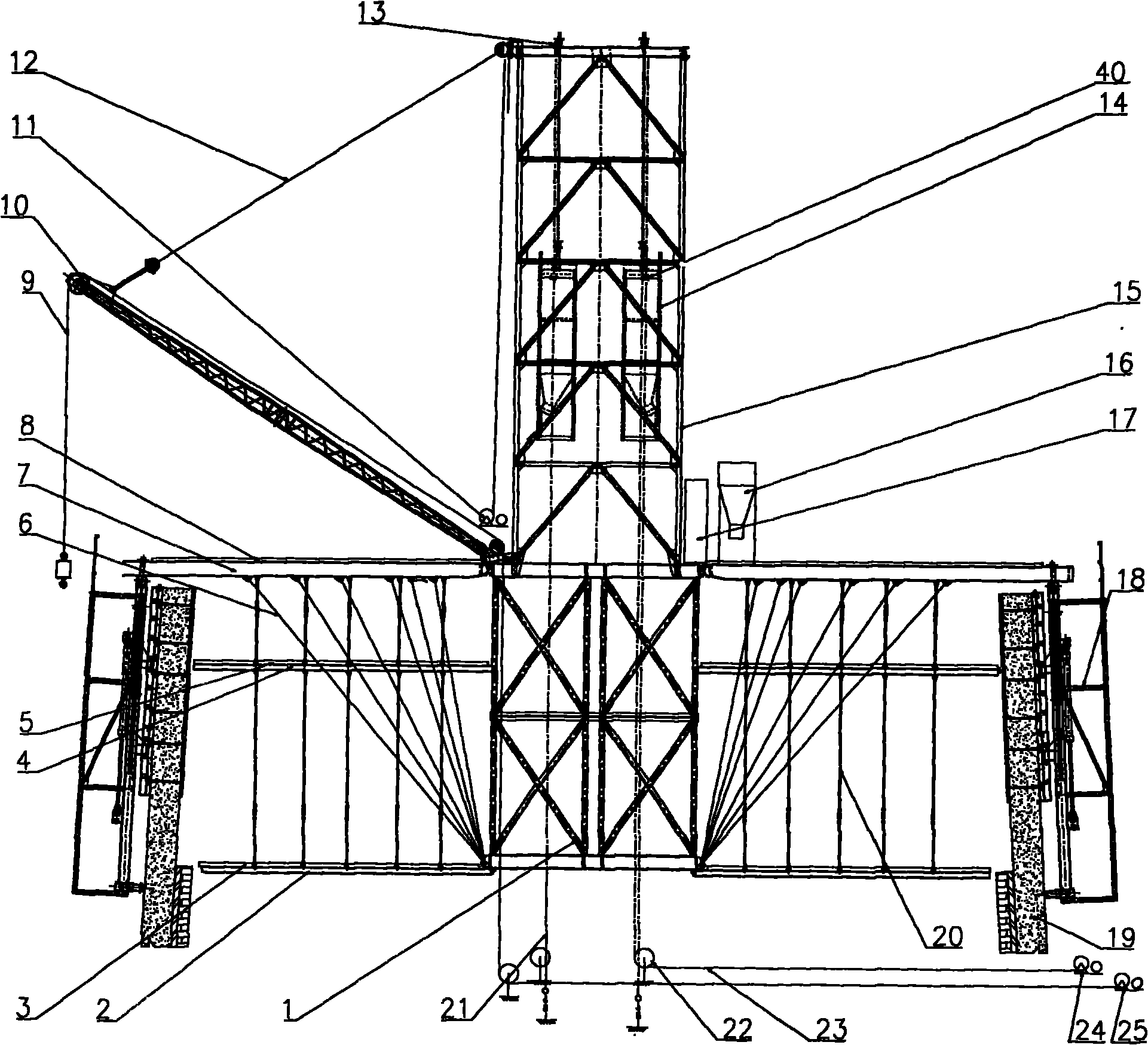
[0028] Such as figure 1 As shown, a chimney hydraulic formwork lifting device includes a lifting derrick and platform system, a hydraulic lifting system 18, a formwork system, a crane system and an electrical system 17. This device is arranged on the upper part of the chimney wall 19, and the hydraulic lifting system 18 passes through The formwork system is installed on the chimney tube wall 19, the crane system and the electrical system 17 are respectively installed on the elevating derrick and the platform system, and the electrical system 17 is connected with the hydraulic lifting system 18 and the crane system respectively.

[0029] The rising derrick and platform system includes central drum ring 1, bricklaying platform radiating beam 2, bricklaying platform 3, formwork platform radiating beam 4, formwork platform 5, radiating beam cable 6, radiati...


PUM


Abstract

The invention relates to a chimney hydraulic mould lifting device, which comprises a lifting derrick, a platform system, a hydraulic lifting system, a template system, a crane system and an electricalsystem, wherein the lifting derrick and the platform system are arranged on the upper part of a chimney and connected with the hydraulic lifting system; the hydraulic lifting system is arranged on the chimney cylinder body through the template system; the crane system and the electrical system are arranged on the lifting derrick and the platform system respectively; and the electrical system is connected with the hydraulic lifting system and the crane system respectively. The device uses lifting mechanisms evenly distributed around the cylinder wall to gradually lift, and the lifting mechanisms can automatically balance and adjust the pressure through the hydraulic system in the lifting process. The device is suitable for the outer cylinder construction of single-cylinder type reinforcedconcrete chimneys or double-cylinder and multi-cylinder chimneys and can be used in structures, such as silos and the like. The device has the advantages of simple and compact structure, easy layout,lighter weight, convenient processing and manufacture, safe assembling and disassembling process, simpleness, convenience, and smooth operation.

Description

technical field [0001] The invention relates to a lifting device, in particular to a chimney hydraulic mold lifting device. Background technique [0002] At present, the construction equipment for chimneys of thermal power plants mainly include sliding formwork and electric lifting formwork. However, the sliding form construction method has four common quality problems, namely, center drift, cylinder torsion, indentation, and surface cracking of the cylinder. The construction of the derrick requires multiple cable wind ropes, which occupies a large area, high labor intensity, and low efficiency. Disadvantages of large loss; poor synchronization of electric sliding mode lifting, lead screw and nut are fragile and inconvenient to check, and poor safety. Contents of the invention [0003] The purpose of the present invention is to overcome the deficiencies of the above-mentioned prior art, and provide a chimney hydraulic mold lifting device with simple and compact structure,...

Claims


Application Information

Patent Timeline
Patent Type & Authority Patents(China)
IPC IPC(8): E04G11/20
Inventor 施发扬仉健康吴庆富孟庆芹刘兰荣王永新
Owner POWERCHINA SEPCO1 ELECTRIC POWER CONSTR CO LTD
Learn More