
Tube bending machine and clamping mechanism thereof

A technology of clamping mechanism and pipe bending machine, which is applied in the field of pipe bending equipment, and can solve the problems of inconvenience and lack of structure of general products

Active Publication Date: 2009-10-28
WISE WELDING TECH & ENG
View PDF0 Cites 19 Cited by
  • Summary
  • Abstract
  • Description
  • Claims
  • Application Information

AI Technical Summary

Problems solved by technology

[0005] This shows that the above-mentioned existing pipe bender obviously still has inconvenience and defects in structure and use, and needs to be further improved urgently.
In order to solve the problems of the pipe bending machine, the relevant manufacturers have tried their best to find a solution, but no suitable design has been developed for a long time, and the general products do not have a suitable structure to solve the above problems, which is obvious. It is a problem that relevant industry players are eager to solve

Method used


Image

  • Tube bending machine and clamping mechanism thereof
  • Tube bending machine and clamping mechanism thereof
  • Tube bending machine and clamping mechanism thereof

Examples


Embodiment Construction

[0030] In order to further explain the technical means and effects of the present invention to achieve the intended purpose of the invention, the specific implementation, structure, and structure of the pipe bender and its clamping mechanism proposed in accordance with the present invention will be described with reference to the accompanying drawings and preferred embodiments. The characteristics and effects are explained in detail.

[0031] See Figure 4 Shown is a schematic plan view of a preferred embodiment of the pipe bender of the present invention. The pipe bender 3 of the preferred embodiment of the present invention is used to bend the metal pipe 5, including, along the transport path 6 of the metal pipe 5, an upsetting mechanism 40 installed on the bed 10, two boosting mechanisms 30, and a rotary Structure 20 and two clamping mechanisms 50. Wherein, when the metal tube 5 is bent, the upsetting mechanism 40 clamps the metal tube 5 and provides an axial pushing force; one...


PUM


Abstract

The invention relates to a tube bending machine and a clamping mechanism thereof. The tube bending machine comprises: a heading mechanism installed on a bed piece along a metal tube transportation path, two boosting mechanisms, rotary structures and two clamping mechanisms, wherein when the metal tube is bent, the heading mechanism holds the metal tube and provides an axial driving force. One of the two clamping mechanisms protrudes under the metal pipe and clamps the metal tube from the side, and one of the two boosting mechanisms pushes against the metal tube. The clamping mechanism comprises: a side snap gauge, an elastic support rod and a boosting part. One side of the side snap gauge is hinged on the end part of the elastic support rod, and the other side thereof pushes against the boosting part. When the boosting part drives the side snap gauge and the elastic support rod to move toward the metal tube and the elastic support rod is blocked, the elastic support rod is elastically deformed along the axial direction, while the side snap gauge revolves around the end part of the elastic support rod under the impetus of the boosting part. The tube bending machine is capable of successively bending bilateral snake-like bends.

Description

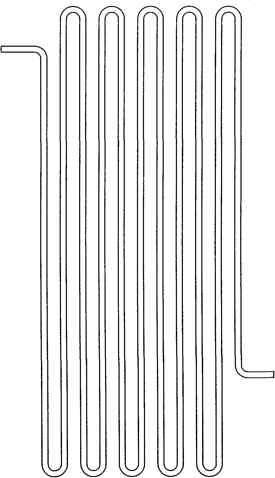
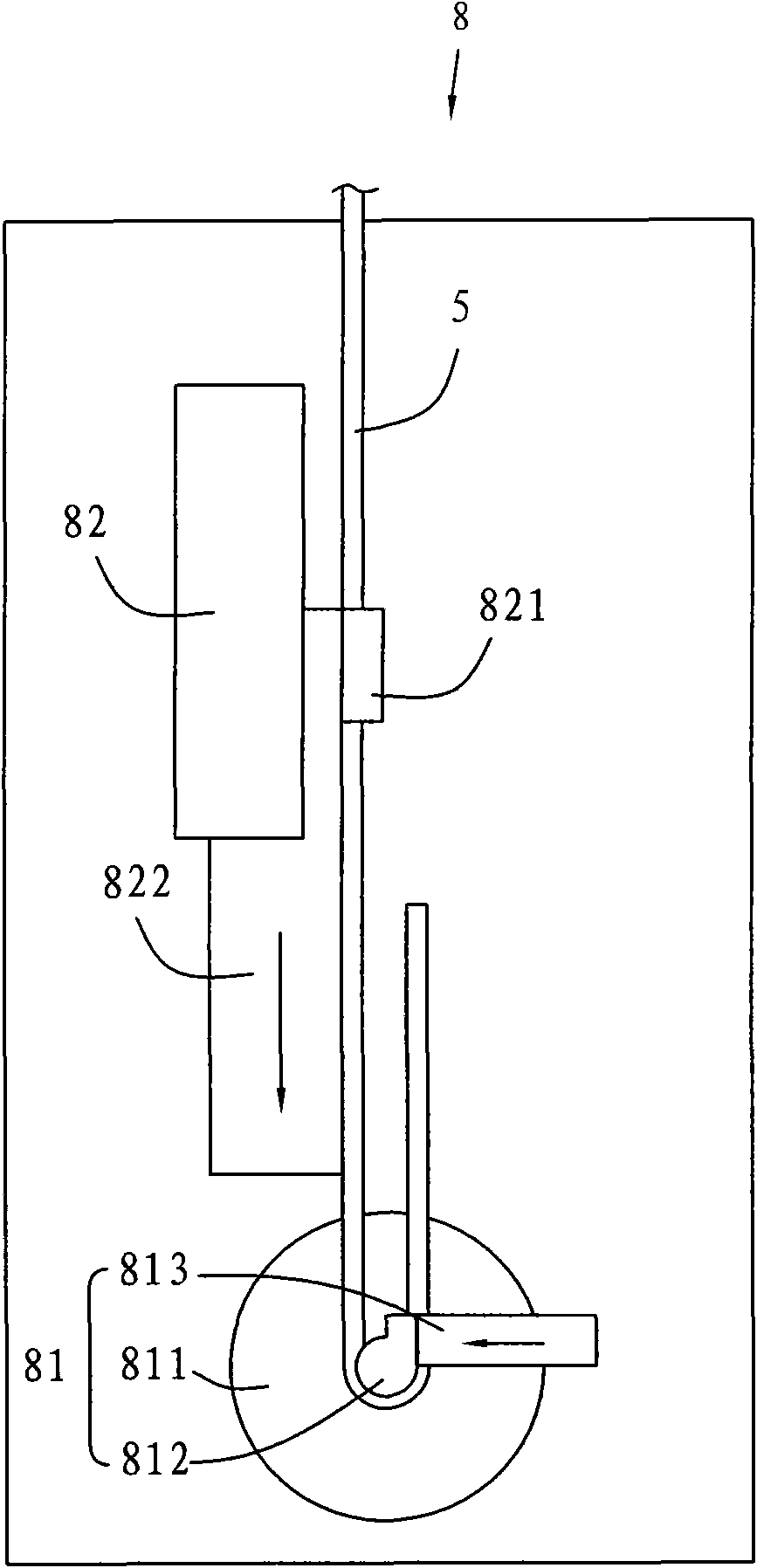
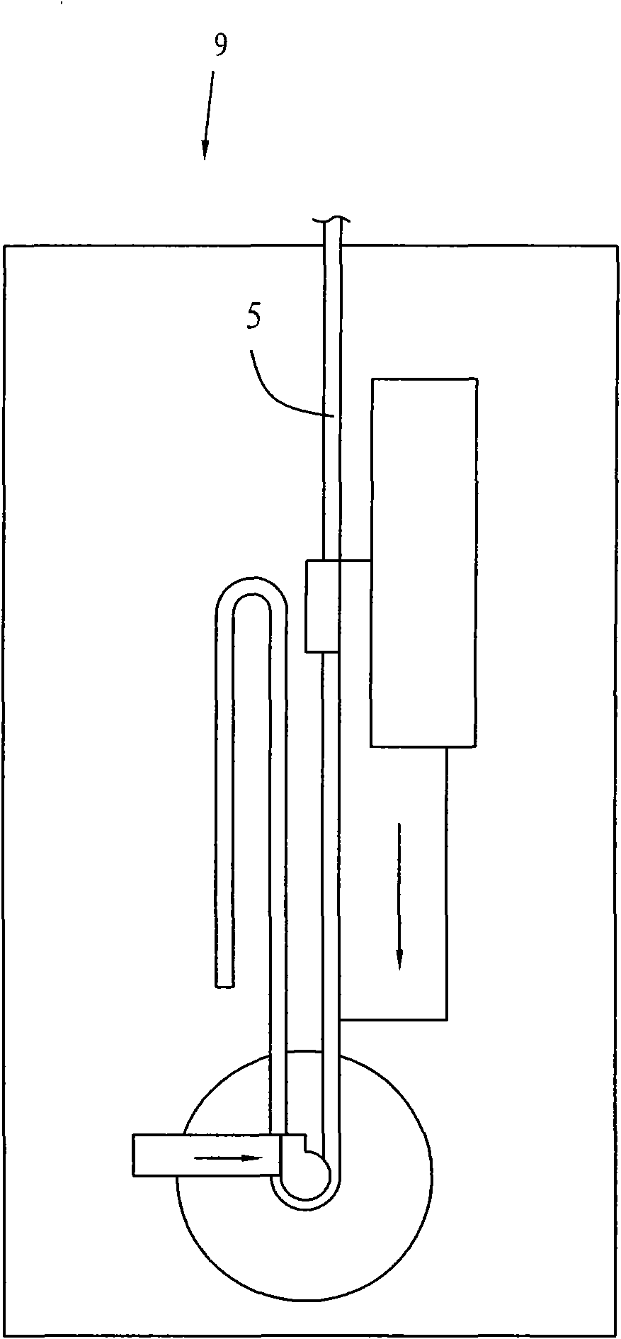
Technical field [0001] The invention relates to a pipe bending device, in particular to a pipe bending machine for bending a double-sided serpentine pipe bending machine and a clamping mechanism thereof. Background technique [0002] In industry, it is often necessary to bend the metal pipe into a serpentine (or S-shaped) bend. Such as figure 1 Shown is a schematic diagram of a single R double-sided serpentine elbow. [0003] See figure 2 Shown is a schematic diagram of an existing pipe bender. The existing pipe bender 8 includes a revolving structure 81 and an upsetting assisting mechanism 82. Among them, the revolving structure 81 includes a revolving body 811; a bending die 812 provided on the revolving body 811; a side clamping tube mechanism 813 provided on one side of the bending die 812; wherein the top upsetting assist mechanism 82 includes a top upsetting mechanism 821 and booster 822. [0004] Such as figure 2 , image 3 Shown is a schematic diagram of a double-sided...

Claims


Application Information

Patent Timeline
Patent Type & Authority Applications(China)
IPC IPC(8): B21D7/16B21D7/02
Inventor 王文乐王际为
Owner WISE WELDING TECH & ENG
Learn More