Optical system

A technology of optical systems and optical components, applied in optics, optical components, instruments, etc., can solve the problem that it is impossible to realize the close image of the observer

Active Publication Date: 2009-10-21
NAT INST OF INFORMATION & COMM TECH
View PDF2 Cites 10 Cited by
  • Summary
  • Abstract
  • Description
  • Claims
  • Application Information

AI Technical Summary

Problems solved by technology

[0003] The mirror image reflected in the plane mirror is imaged inside the mirror that is in a symmetrical relationship with the mirror surface and the object (projected object). Therefore, it is impossible for the observer to approach the image by extending his hand to the image.

Method used


Image

  • Optical system
  • Optical system
  • Optical system

Examples


Embodiment Construction

[0019] Hereinafter, embodiments of the present invention will be described with reference to the drawings.

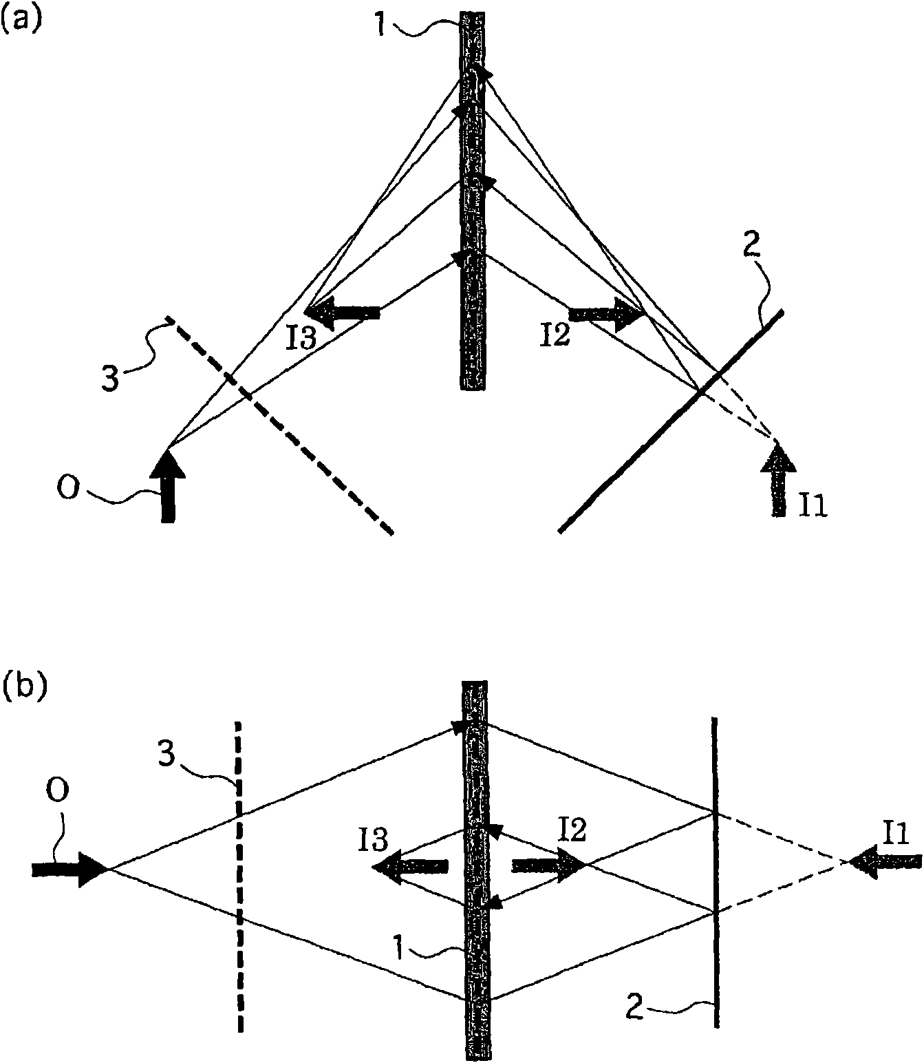
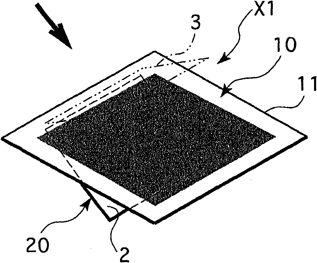
figure 2 The first embodiment of the present invention shown is an optical system X1. It is composed of a reflective surface-symmetric imaging element 10 having a curved surface with an imaging function that allows light to pass through and forming a real image at a surface-symmetrical position, and a surface-symmetric imaging element 10 disposed in the substrate. The projection object O is constituted by a plane mirror 20 on the opposite side of the reflective surface-symmetric imaging element 10 sandwiching it. Hereinafter, the structure and imaging method of each part of the optical system X1 will be described.

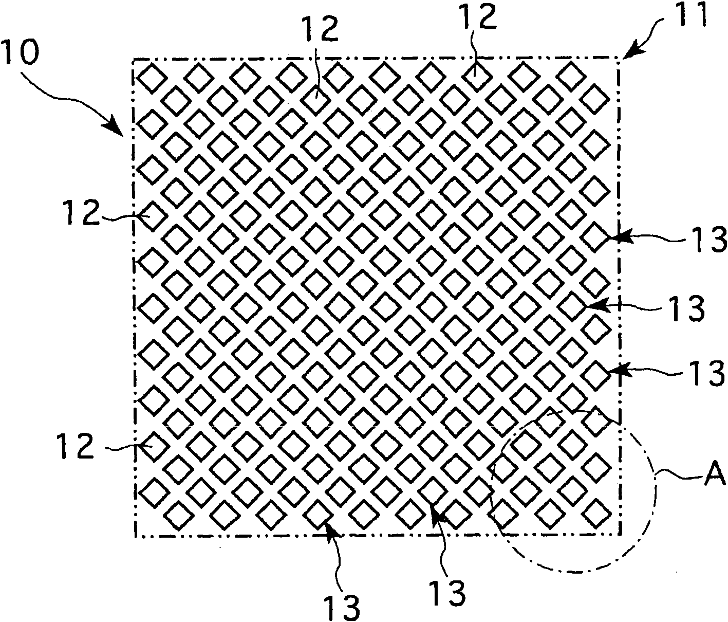
[0020] Such as figure 2 with image 3 As shown, the reflective surface-symmetric imaging element 10 is provided with a flat substrate 11 on which a plurality of holes 12 perpendicular to the surface of the flat substrate and penetrating the thickness of the sh...


PUM


Abstract

An optical system, having a novel image forming method that an image identical to one produced by reflecting an object of projection on a mirror is formed in a space where a mirror does not actually exist, is constituted as an optical system comprising a light beam refracting surface having actions of allowing light to pass through it while refracting it and forming a real image at a plane-symmetric position, and a mirror plane disposed facing this light beam refracting surface such that an image of an object of projection disposed on an observation side opposite to the mirror plane across the light beam refracting surface is formed at a position where it is reflected on an unsubstantial virtual mirror moved to the plan-symmetric position of the mirror plane with respect to the light beam refracting surface by allowing light emitted from the object of projection to pass through the light beam refracting surface, to be reflected off the mirror plane and again to pass through the light beam refracting surface.

Description

Technical field [0001] The present invention relates to a novel optical system with a mirror function utilizing light transmission and reflection. Background technique [0002] When the image is reflected in a flat mirror, the observer’s eyes see the reflected light on the mirror surface as if it comes from a direction extending into the mirror. Therefore, the image reflected in the flat mirror (mirror image) is a virtual image formed in the mirror (for example, Refer to Non-Patent Document 1). Non-Patent Document 1: Online search for "Virtual image", WIKIPEDIA (English version), [Search on October 23, Heisei 18], Internet URL <URL:httpl / / en.wikipedia.org / wiki / Virtua1_image> [0003] The mirror image reflected in the flat mirror is imaged inside the mirror that is in a plane symmetric relationship with the object (projected object) with respect to the mirror surface. Therefore, it is impossible for the observer to approach the image by stretching his hand toward the image...

Claims


Application Information

Patent Timeline
Patent Type & Authority Applications(China)
IPC IPC(8): G02B17/08G02B5/08
CPCG02B1/007G02B5/136G02B17/006G02B5/124G02B17/008G02B27/2292G02B30/56G02B17/08G02B5/08
Inventor 前川聪
Owner NAT INST OF INFORMATION & COMM TECH
Why Eureka
Try Eureka