Method, device and system for calculating service path
A technology of business paths and paths, applied in the network field
- Summary
- Abstract
- Description
- Claims
- Application Information
AI Technical Summary
Problems solved by technology
Method used
Image


Examples
Embodiment 1
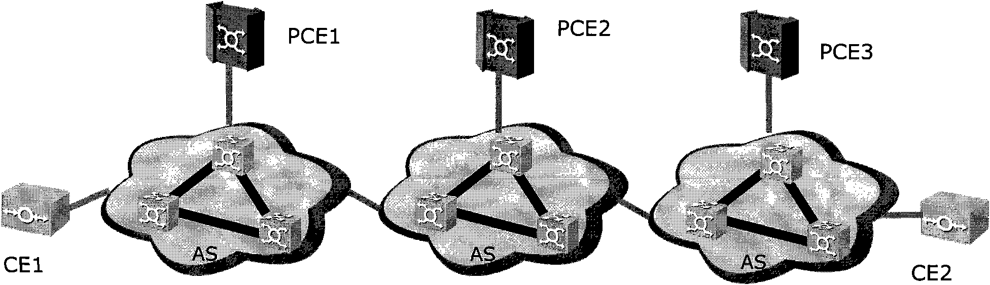
[0043] For the convenience of illustration, establish as image 3 The network topology shown includes: an autonomous system, a client device edge node, a network edge node, and a path computation unit. Wherein, the autonomous systems include: AS1, AS2, AS3, AS4, AS5 and AS6. Client equipment nodes include: CE1 and CE2. The network edge nodes include: PE1 and PE2. The path computation units include: PCE1, PCE2, PCE3, PCE4, PCE5 and PCE6. PE1 is the network edge node of AS1, and PE2 is the network edge node of AS2. And the next-hop PCEs of PCE1 are PCE2 and PCE3, the next-hop PCEs of PCE3 are PCE4 and PCE5, the next-hop PCEs of PCE4 are PCE6, and the next-hop PCEs of PCE5 are PCE6; correspondingly, the previous-hop PCEs of PCE6 They are PCE4 and PCE5. The last hop PCE of PCE4 is PCE3, the last hop PCE of PCE5 is PCE3, the last hop PCE of PCE3 is PCE1, and the last hop PCE of PCE2 is PCE1.
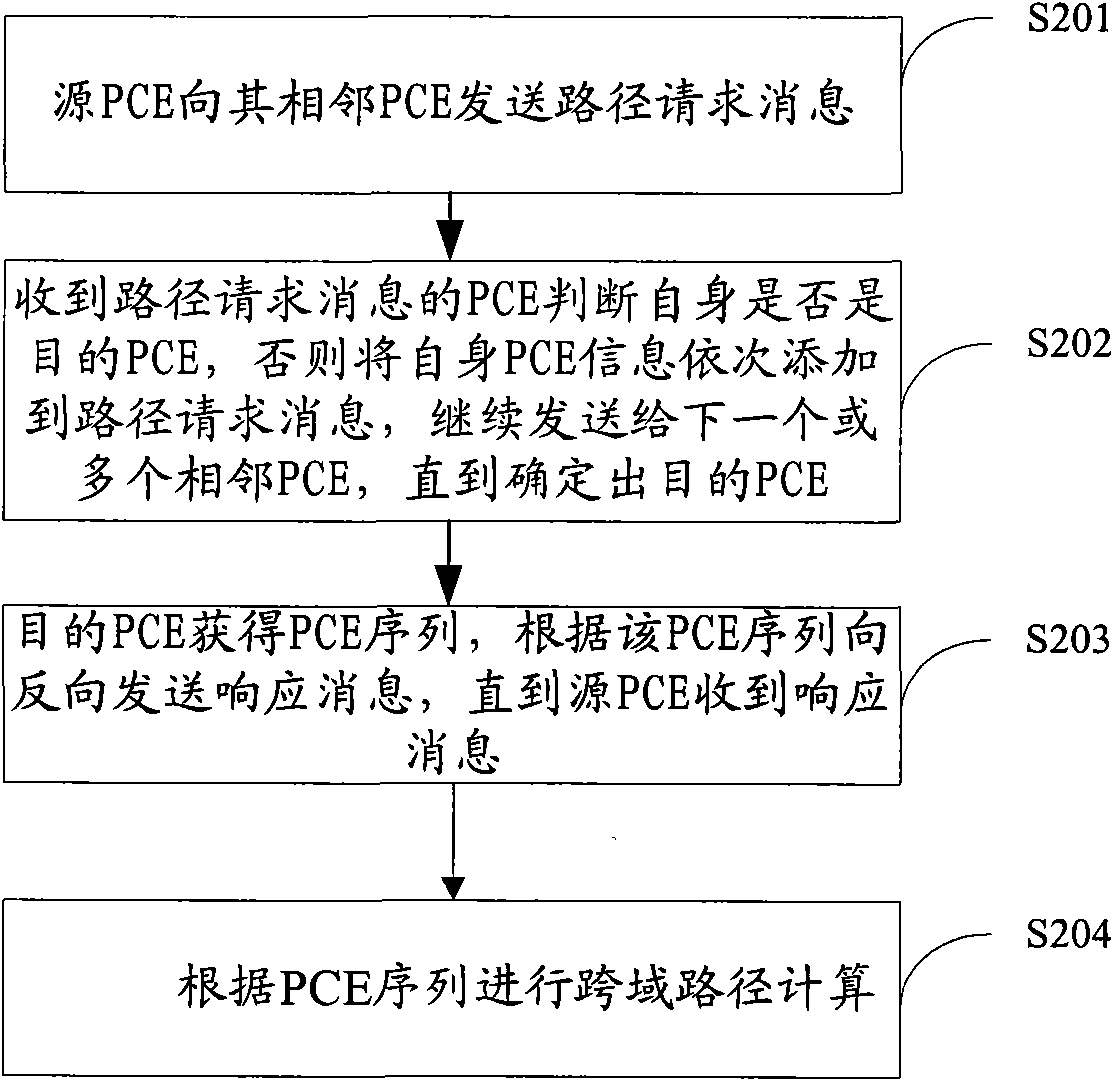
[0044] Such as Figure 4 As shown, it is a schematic flowchart of a method for calc...
Embodiment 3
[0094] Embodiment 3 of the present invention, a route calculation unit for implementing service route calculation, including:
[0095] A receiving module, configured to receive a path request message, where the path request message includes a service destination node;
[0096] The first module, if the path request message received by the receiving module is from a service source node, after adding the PCE information of the belonging PCE to the path request message, send it to the adjacent PCE;
[0097] A judging module, if the path request message received by the receiving module is from an adjacent PCE, judging whether the service destination node belongs to the autonomous system of the PCE;
[0098] The second module, if the judgment result of the judging module is no, then continue to send the information of the associated PCE to the path request message to the next one or more adjacent PCEs;
[0099] The third module, if the judgment result of the judging module is yes, ...
Embodiment 4
[0104] Embodiment 4 of the present invention, a network system for realizing service path calculation, including:
[0105] The first PCE is configured to receive the path request message carrying the service destination node information sent by the source node, add the source PCE information to the path request message and then send the path request message to its adjacent intermediate PCE;
[0106] The second PCE is used to determine whether the service destination node belongs to the autonomous system of this PCE after receiving the path request message, and if not, add its own PCE information to the path request message in turn and continue sending it to its neighbors other second PCE; if yes, add self PCE information to the path request message, obtain the PCE sequence from the source PCE to the destination PCE, and send a response message carrying the PCE sequence in the reverse direction according to the PCE sequence, ;
[0107] Wherein, the second PCE is further config...
PUM
 Abstract
Description
Claims
Application Information
 - R&D
- Intellectual Property
- Life Sciences
- Materials
- Tech Scout
- Unparalleled Data Quality
- Higher Quality Content
- 60% Fewer Hallucinations
Browse by: Latest US Patents, China's latest patents, Technical Efficacy Thesaurus, Application Domain, Technology Topic, Popular Technical Reports.
© 2025 PatSnap. All rights reserved.Legal|Privacy policy|Modern Slavery Act Transparency Statement|Sitemap|About US| Contact US: help@patsnap.com