
Adjustable high speed electro-optical attenuator

An attenuator, electro-optical technology, applied in the field of optical communication, can solve the problems of increased cost, complex manufacturing process, VOA adjustment accuracy and response speed can not well meet the requirements of the rapid development of optical communication, etc., to achieve precise control and high speed. The effect of dynamic adjustment

Inactive Publication Date: 2010-12-22
ZHEJIANG UNIV
View PDF0 Cites 0 Cited by
  • Summary
  • Abstract
  • Description
  • Claims
  • Application Information

AI Technical Summary

Problems solved by technology

However, the traditional mechanical VOA or MEMS-based VOA technology, due to the limitation of its own structural design factors, the adjustment accuracy and response speed of VOA cannot well meet the requirements of the rapid development of optical communication.
Moreover, traditional mechanical VOAs and MEMS-based VOAs increase their costs due to the relatively complex manufacturing process

Method used


Image

  • Adjustable high speed electro-optical attenuator
  • Adjustable high speed electro-optical attenuator
  • Adjustable high speed electro-optical attenuator

Examples


Embodiment Construction

[0017] Further illustrate the present invention below in conjunction with accompanying drawing:

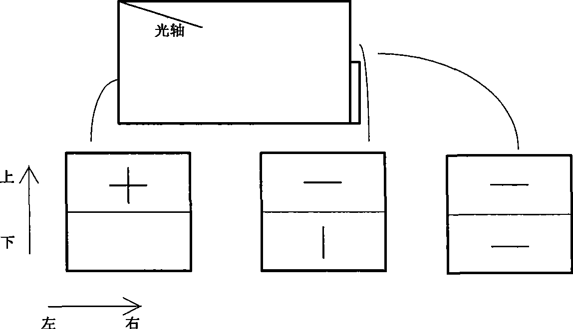
[0018] Such as figure 1 As shown, a high-speed adjustable electro-optic attenuator is to place a fiber collimator 1, a first birefringent crystal 2, a first half-wave plate 3, an electro-optic angle deflector 4, and a deflector A prism 5, a second half-wave plate 6, a second birefringent crystal 7, and a second fiber collimator 8, which collimate and couple the optical signal emitted by the first fiber collimator to the second fiber collimator. By controlling the applied voltage of the electro-optical angle deflection plate, the optical power of the optical signal coupled into the second fiber collimator is changed, thereby realizing a high-speed adjustable electro-optic attenuator.

[0019] The material of the electro-optical angle deflector 4 is transparent ferroelectric ceramics. The transparent ferroelectric ceramics may be lead lanthanum zirconate titanate ceramics or lead...


PUM


Abstract

The invention discloses an adjustable high speed electro-optical attenuator. A first optical fiber collimator, a first birefringent crystal, a first 45-degrees half-wave plate, an electro-optical angle deviation plate, a deviation prism, a second 45-degree half-wave plate, a second birefringent crystal and a second optical fiber collimator are arranged on the direction of an identical horizontal optical path in sequence; optical signals emitted by the first optical fiber collimator are collimated and coupled with the second optical fiber collimator; the capacity of optical power of the optical signals coupled into the second optical fiber collimator is changed through controlling the applied voltage of the electro-optical angle deviation plate, thereby the adjustable high speed electro-optical attenuator is achieved. Compared with the traditional art, the invention has the advantages of simple and compact structure, high speed, low cost, easy implementation and the like.

Description

technical field [0001] The invention relates to the field of optical communication, in particular to a high-speed adjustable electro-optic attenuator. Background technique [0002] A variable optical attenuator (VOA) is a device used to attenuate optical power. Because the optical receiver in the system has a certain power range, when the input optical power is too large, it must be attenuated by an optical attenuator. More importantly, it can accurately and actively balance the optical energy in the communication system, especially the wide application of DWDM and EDFA in optical communication, gain flattening or channel power equalization, etc., which make VOA an indispensable key device in optical communication systems . [0003] At present, VOA tunable optical attenuator technology can be roughly divided into: discrete micro-optical component technology, MEMS technology and optical waveguide technology. Discrete micro-optical technology can be divided into mechanical,...

Claims


Application Information

Patent Timeline
Patent Type & Authority Patents(China)
IPC IPC(8): G02F1/03G02F1/05G02B5/04G02B1/02
Inventor 章飞金晓峰冀军章献民池灏
Owner ZHEJIANG UNIV
Learn More