
Motorcycle crankcase cover structure

A crankcase cover, motorcycle technology, applied in the direction of engine components, machines/engines, adding/discharging lubricants, etc., can solve the problems of crankshaft running stability decline, cumbersome operation, shortened crankshaft service life, etc., and achieve dynamic balance. Affected, simple and quick operation, and prolonging the effect of service life

Inactive Publication Date: 2009-09-23
力帆科技(集团)股份有限公司
View PDF6 Cites 3 Cited by
  • Summary
  • Abstract
  • Description
  • Claims
  • Application Information

AI Technical Summary

Problems solved by technology

There is a serious use defect in the above structure: when the engine clutch needs to be repaired or replaced, the entire engine crankcase cover must be disassembled. The dynamic balance of the crankshaft, on the one hand, the crankcase cover gasket must be replaced every time it is removed, which is extremely costly; on the other hand, it will reduce the stability of the crankshaft operation and increase the vibration of the engine
Since the centrifugal oil filter is located in the crankcase, when maintenance or replacement is required, the crankcase cover and the crankshaft must be disassembled. The dynamic balance of the crankshaft reduces the stability of the crankshaft, which not only increases the vibration of the engine, but also shortens the service life of the crankshaft.

Method used


Image

  • Motorcycle crankcase cover structure
  • Motorcycle crankcase cover structure
  • Motorcycle crankcase cover structure

Examples


Embodiment Construction

[0028] Below in conjunction with accompanying drawing and embodiment the present invention will be further described:

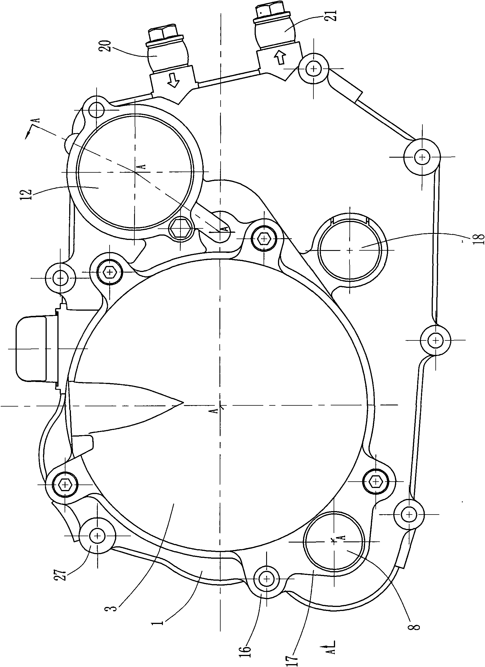
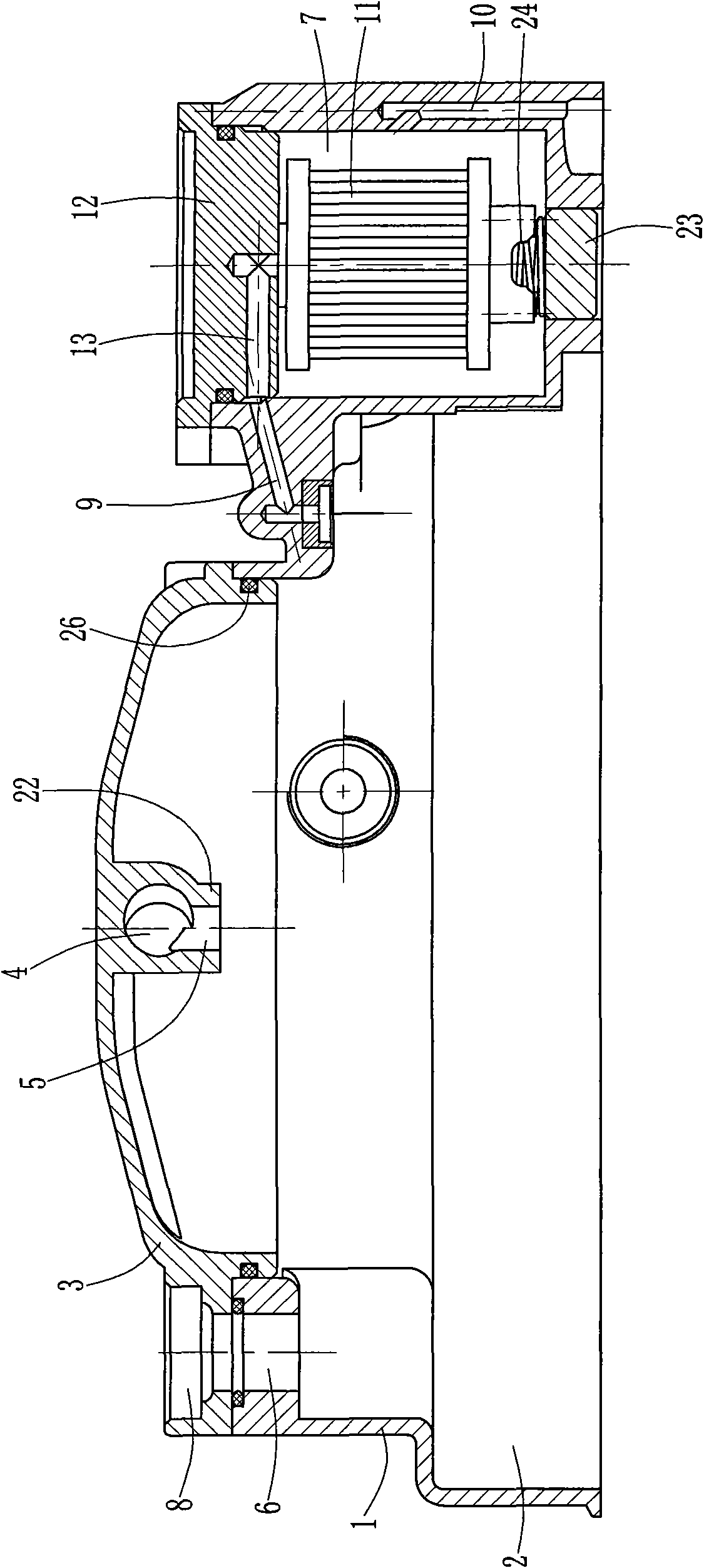
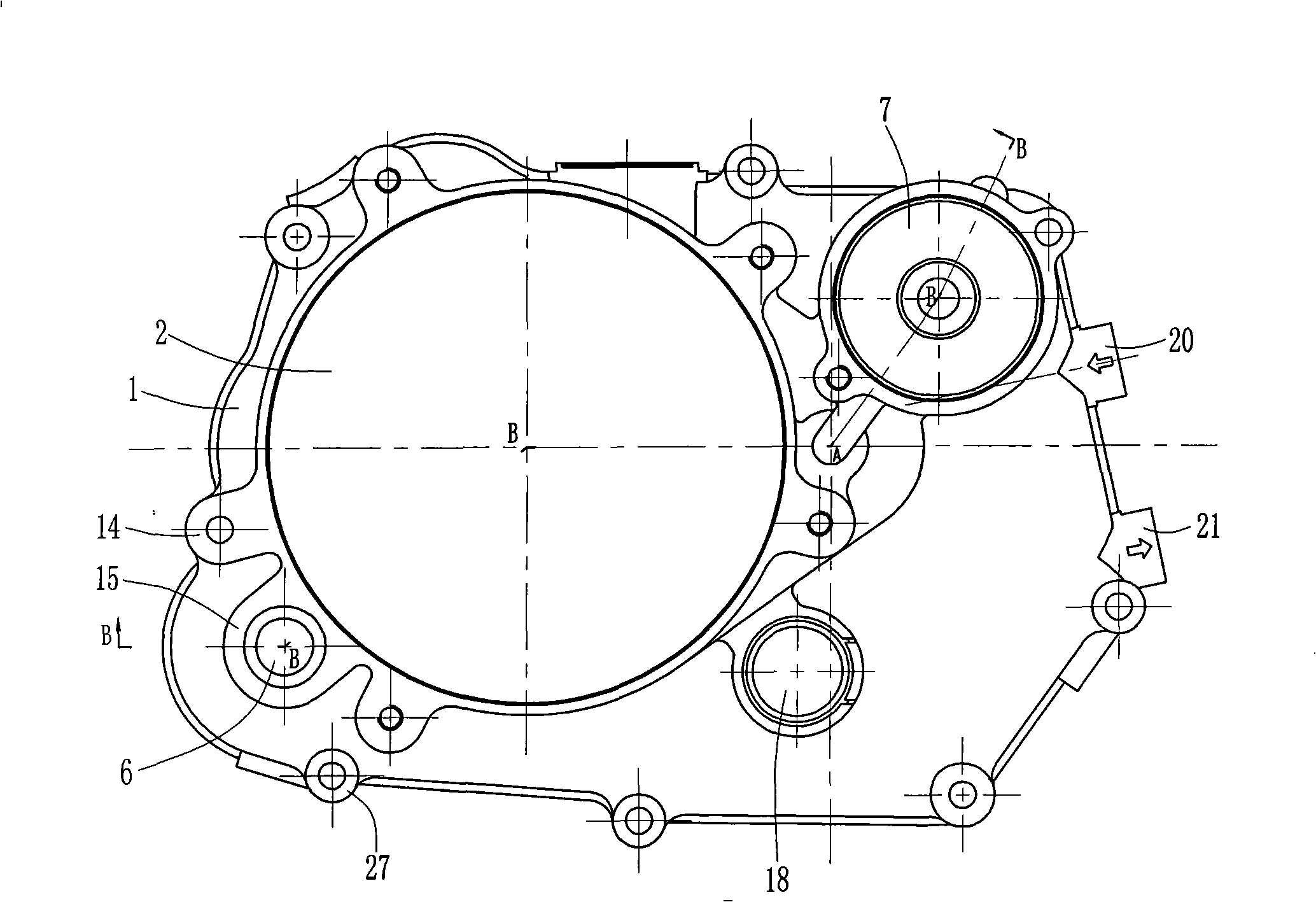
[0029] Such as figure 1 , figure 2 , image 3 , Figure 4 , Figure 5 Shown, the present invention is made of parts such as crankcase cover 1, clutch release cover 3, filter core 11 and engine oil filter cover 12 by band inner chamber 2, and wherein the front end opening of crankcase cover 1, the shape size of opening and The combined end face of the crankcase body is compatible, and a plurality of mounting posts 27 are distributed on the open outer edge, and the crankcase cover 1 is fixed to the crankcase by screws passing through the mounting posts 27 and the corresponding mounting holes on the crankcase body. physically. The top of the crankcase cover 1 is provided with an oil filling hole 19, which communicates with the inner cavity 2 of the crankcase cover 1, and can directly inject machine oil into the crankcase through the oil filling hole 19. T...


PUM


Abstract

The invention relates to a motorcycle crankcase cover structure. The rear end of a crankcase cover is provided with a window which is sealed by a clutch separate cover, the clutch separate cover is provided with a control rod hole along the radial direction, and the control rod hole is communicated with the inner cavity of the crankcase cover through a push rod hole; a first via hole for a starting shaft and a containing groove are arranged beside the window of the crankcase cover, wherein the first via hole for the starting shaft is butt-jointed and communicated with a second via hole for the starting shaft on the clutch separate cover, the groove wall of the containing groove is respectively provided with an oil inlet and an oil outlet, a filter element is arranged inside the containing groove, and a notch of the containing groove is sealed by an oil filter cover; and the oil filter cover is provided with an oil conduit, an inlet of the oil conduit is communicated with the inner cavity of the crankcase cover by the oil inlet, and an outlet thereof is communicated with the interior of the filter element. The motorcycle crankcase cover structure provides convenience for the maintenance and replacement of the clutch and filter element, leads operations of the repair and replacement of the clutch, or the cleaning and replacement of the filter element to be simpler and faster, and ensures the sealing property of the crankcase and the dynamic balance of the crankshaft not to be affected.

Description

technical field [0001] The invention relates to an engine part, in particular to a motorcycle crankcase cover structure on the engine. Background technique [0002] At present, the traditional crankcase cover is an integral structure with an open front end and a closed rear end. The clutch lever and push rod are installed on the closed end of the crankcase cover, and the two are connected to each other, so that the action of the clutch lever is transmitted to the crankcase through the push rod. clutch to control clutch disengagement or engagement. There is a serious use defect in the above structure: when the engine clutch needs to be repaired or replaced, the entire engine crankcase cover must be disassembled. For the dynamic balance of the crankshaft, on the one hand, the crankcase cover gasket must be replaced every time it is disassembled, which is extremely costly; on the other hand, it will reduce the stability of the crankshaft and increase the vibration of the engin...

Claims


Application Information

Patent Timeline
Patent Type & Authority Applications(China)
IPC IPC(8): F02F7/00F01M1/10F01M11/04
Inventor 李力唐勇
Owner 力帆科技(集团)股份有限公司
Learn More