
Refrigeration device

A refrigeration device and refrigerant technology, applied in refrigerators, refrigeration components, refrigeration and liquefaction, etc., can solve the problems of insufficient refrigerant flow in heat exchangers and inability to perform reliable operation

Active Publication Date: 2011-02-16
DAIKIN IND LTD
View PDF1 Cites 0 Cited by
  • Summary
  • Abstract
  • Description
  • Claims
  • Application Information

AI Technical Summary

Problems solved by technology

As a result, there will be a problem that the refrigerant flow rate of the heat exchanger is insufficient due to the bias flow of the refrigerant in this type of refrigeration device, and reliable operation cannot be performed.

Method used


Image

  • Refrigeration device
  • Refrigeration device
  • Refrigeration device

Examples


Embodiment Construction

[0043] Hereinafter, embodiments of the present invention will be described in detail based on the drawings.

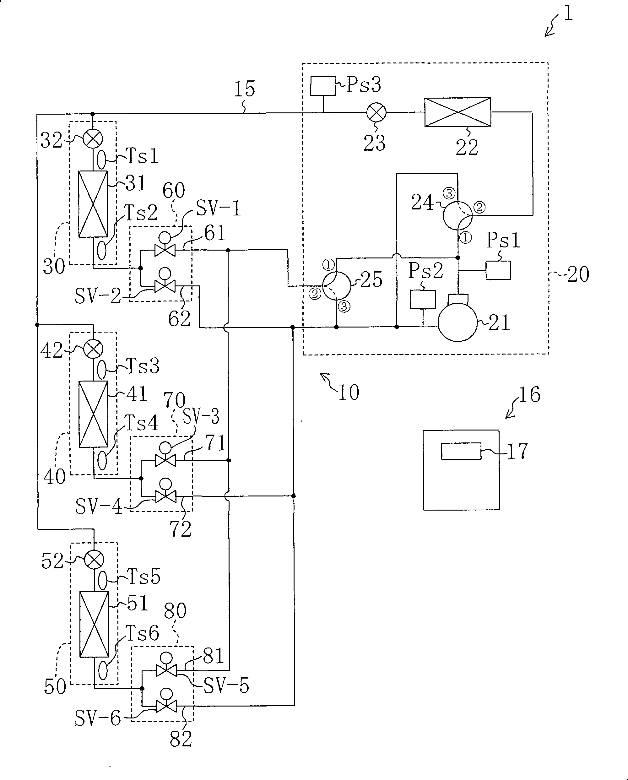
[0044] (First Embodiment of the Invention) The refrigerating apparatus according to the first embodiment of the present invention constitutes an air conditioner 1 capable of individually cooling or heating a plurality of rooms. This air conditioner 1 is capable of cooling another room while heating one room, which is a so-called free-cooling type air conditioner.

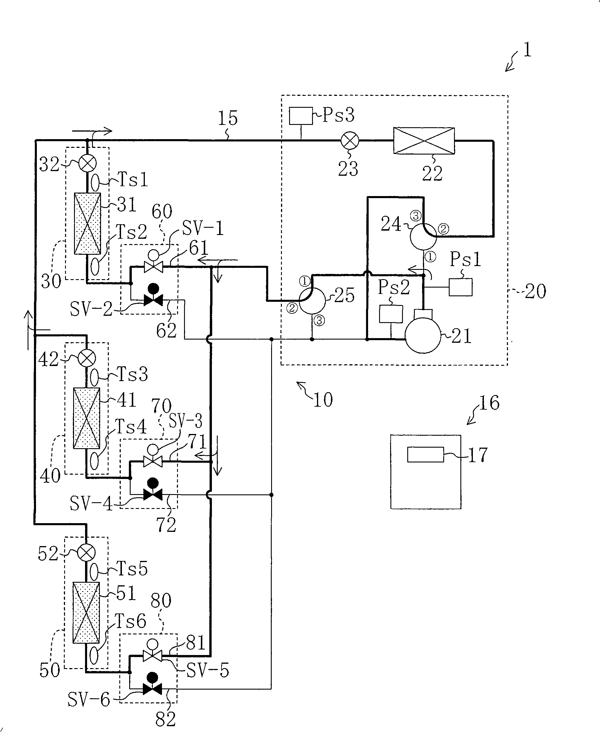
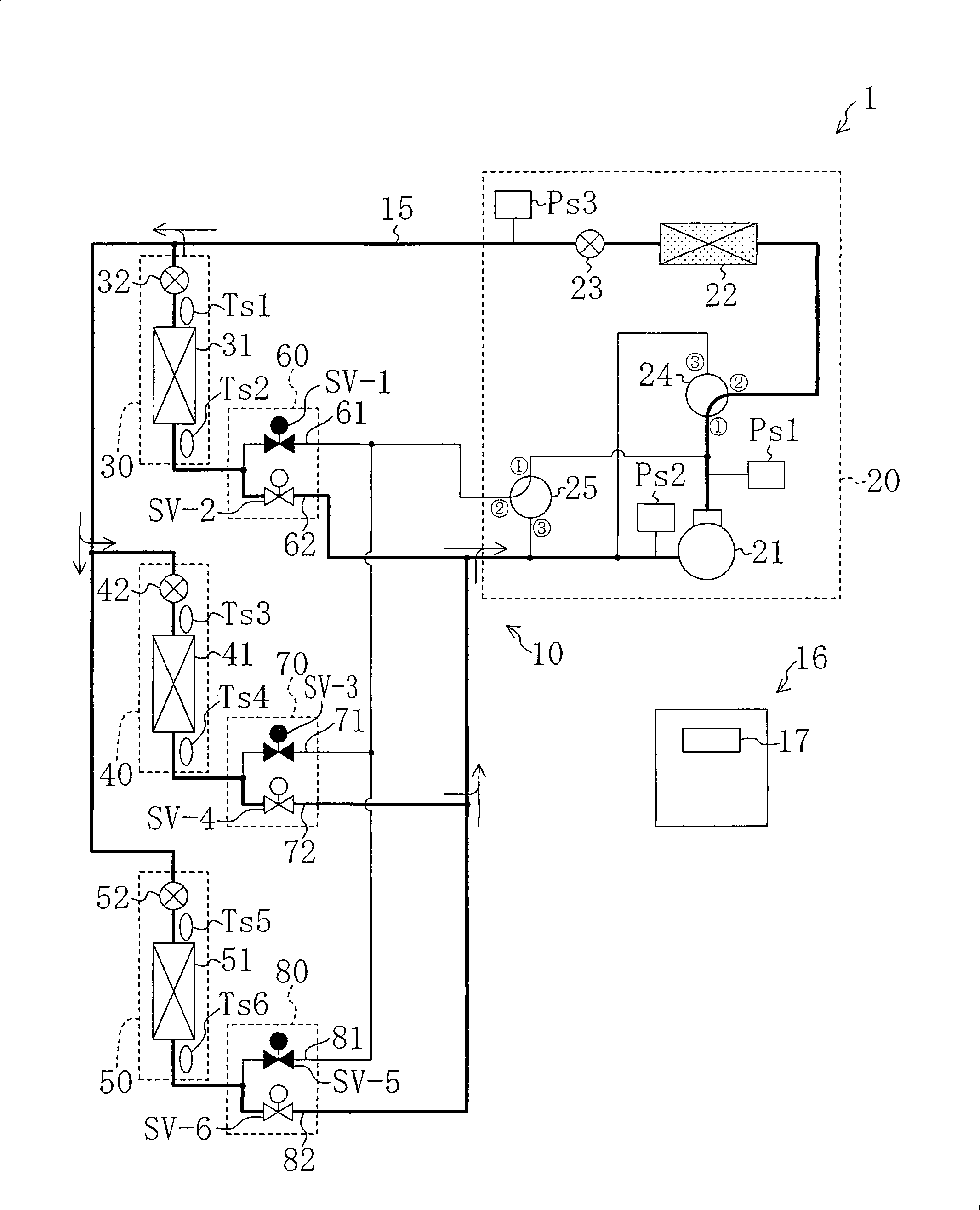
[0045] Such as figure 1 As shown, in the air conditioner 1 of the first embodiment, one outdoor unit 20, three indoor units 30, 40, 50, and three BS units 60, 70, 80 are connected through piping to form a refrigerant circuit 10. In this refrigerant circuit 10, a vapor compression refrigeration cycle is performed by a refrigerant cycle.

[0046] The outdoor unit 20 constitutes a heat source side unit and includes a compressor 21 , an outdoor heat exchanger 22 , an outdoor expansion valve 23 , a first thre...


PUM


Abstract

A refrigeration device in which, in a coexistence operation where a refrigeration cycle using an outdoor heat exchanger (22) as a condenser and also using at least one of indoor heat exchangers (31, 41, 51) as a condenser, a pressure difference Delta<P1> between a high pressure refrigerant and a refrigerant in a liquid tube (15) is detected, and the degree of opening of an outdoor expansion valve(23) is adjusted so that the pressure difference Delta<P1> is higher than a predetermined target level.

Description

technical field [0001] The present invention relates to a refrigerating apparatus including a refrigerant circuit having a plurality of heat exchangers, and more particularly, to countermeasures against a refrigerant flowing to each heat exchanger. Background technique [0002] It is well known that the cooling and heating requirements of the room can be met simultaneously, so-called cooling and heating dual-purpose (free) refrigeration devices. This refrigerating device is configured such that a plurality of utilization-side units are respectively installed in different rooms, and some utilization-side units perform cooling operation while some utilization-side units perform heating operation. [0003] Patent Document 1 discloses such a refrigeration device. Such as Figure 12 As shown, this refrigerating apparatus 100 includes a refrigerant circuit 101 that circulates a refrigerant to perform a refrigerating cycle. The refrigerant circuit 101 is provided with a compresso...

Claims


Application Information

Patent Timeline
Patent Type & Authority Patents(China)
IPC IPC(8): F25B1/00F24F11/02F25B13/00F25B29/00
CPCF25B49/02F25B13/00F25B2313/0253F25B2600/2513F25B2313/007F25B2313/0233F25B2700/1931F25B2313/005F25B2313/0231F25B2400/13F25B2700/1933F25B2313/02732F25B2313/0313
Inventor 河野聪松冈慎也
Owner DAIKIN IND LTD
Learn More