
Star tracker with baffle

A tracker and astrological technology, applied in the field of astrological trackers, can solve problems such as large baffles

Inactive Publication Date: 2013-12-04
NEDERLANDSE ORG VOOR TOEGEPAST-NATUURWETENSCHAPPELIJK ONDERZOEK (TNO)
View PDF4 Cites 0 Cited by
  • Summary
  • Abstract
  • Description
  • Claims
  • Application Information

AI Technical Summary

Problems solved by technology

Therefore, this baffle also has the problem that the baffle must be large while the minimum protection angle must be small

Method used


Image

  • Star tracker with baffle
  • Star tracker with baffle
  • Star tracker with baffle

Examples


Embodiment Construction

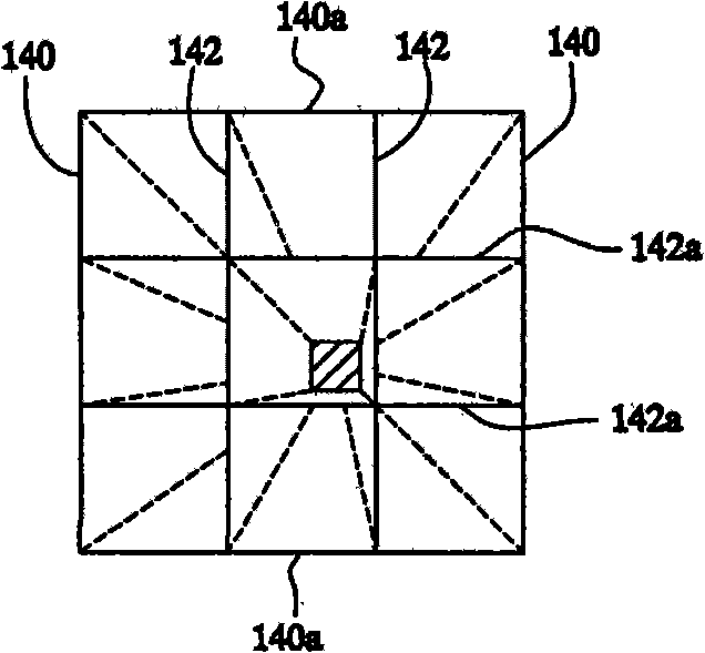
[0029] figure 1 A cross-section of a star tracker is schematically shown. The star tracker comprises an image sensor 10 connected to a computer 11 , an objective lens 12 (shown schematically as a single lens) and a baffle 14 . Baffle 14 includes a wall array including a plurality of side walls 140 and one or more interior walls 142 . Inner wall 142 divides the interior of the baffle into a plurality of compartments. The walls 140, 142 point at non-zero angles relative to each other. exist figure 1 In the instance of , its sections radiate from a virtual common point. Although two inner walls 142 have been shown by way of example, it should be understood that one inner wall 142, or more than two inner walls 142, may be used.

[0030] In operation, light from different stars reaches the star tracker from different directions (indicated by dashed lines 16a, 16b in the figure). Due to the angle between the inner walls 142 of the baffle 14, part of the light from each star is...


PUM


Abstract

A star tracker is used to measure the direction of stars. Preferably a wide imaging range is provided so that a reliable orientation of the star tracker can be computed from measurements of the directions of star at substantially different directions. The star tracker comprises a light baffle and located between the light baffle and an image sensing arrangement. The light baffle comprises an array of walls, including sidewalls and at least one internal wall between the sidewalls. Preferably, the side walls and the at least one internal wall are oriented at mutually different orientations emanating from a virtual line of intersection of the planes of the walls. Thus a range of star directions can be imaged with constant sensitivity.

Description

technical field [0001] The invention relates to a star tracker and a method for measuring the direction towards a celestial body. Background technique [0002] A star tracker can be used to measure the direction towards a selected star. This can be used in space vehicles, for example, to determine the orientation of the space vehicle. [0003] US Patent No. 5,745,869 describes a star tracker. The star tracker images a portion of the sky onto an image sensor. A given star is identified from the patterns of the stars in the image, and the direction of the star is determined from the position of the star in the image. [0004] In order to determine the orientation relative to the stars, it is necessary to determine the orientations of at least two stars with substantially different directions. Usually multiple star trackers are used for this, pointing them at different parts of the sky. In order to obtain precise orientations, the mechanical orientation of these star track...

Claims


Application Information

Patent Timeline
Patent Type & Authority Patents(China)
IPC IPC(8): B64G1/36
CPCG01S3/7867G01S3/781B64G1/361
Inventor 约翰内斯·阿德里安乌斯·彼得鲁斯·莱杰滕斯
Owner NEDERLANDSE ORG VOOR TOEGEPAST-NATUURWETENSCHAPPELIJK ONDERZOEK (TNO)
Learn More