Helical blade rolling mill

A technology of spiral blades and rolling mills, applied in the field of mechanical rolling, which can solve the problems of increasing debugging costs, complex adjustment of blade rolling gaps, and complex adjustments

Inactive Publication Date: 2011-05-11
SHANDONG YUANYOU HEAVY IND SCI & TECH
View PDF0 Cites 0 Cited by
  • Summary
  • Abstract
  • Description
  • Claims
  • Application Information

AI Technical Summary

Problems solved by technology

Therefore, it is more complicated to adjust the rolling gap of the blades. It needs to comprehensively adjust the angle, misalignment, axial movement of the tapered rolls and the relative position between the strip and the rolls. Adjust the position of the installed roll spindle and the position of the strip material. This adjustment structure is complex in design, but easy to adjust
The other is external adjustment, that is, to adjust the position of the installation roll and the bearing seat and the installation position of the strip material. This adjustment structure is relatively simple, but the adjustment is complicated and laborious
Therefore, there are deficiencies in the two kinds of adjustments. In addition, the structural design of the spiral blade mill also has the problem of inconsistent benchmarks, which brings unnecessary difficulties to the adjustment, especially the difficulty of resetting, such as the central axis of the two rolls of the rolling mill. , it is required to be in the same plane, but it is difficult to meet this requirement after installation, and it is not easy to detect
Therefore, the spiral blade rolling is restricted by the commissioning cost, that is to say, a spiral blade rolling mill only rolls one or a few kinds of blades, so that the commissioning cost can be reduced to the minimum, otherwise the commissioning cost will be greatly increased, or the equipment will be increased invest, no other way

Method used


Image

  • Helical blade rolling mill
  • Helical blade rolling mill
  • Helical blade rolling mill

Examples


Embodiment Construction

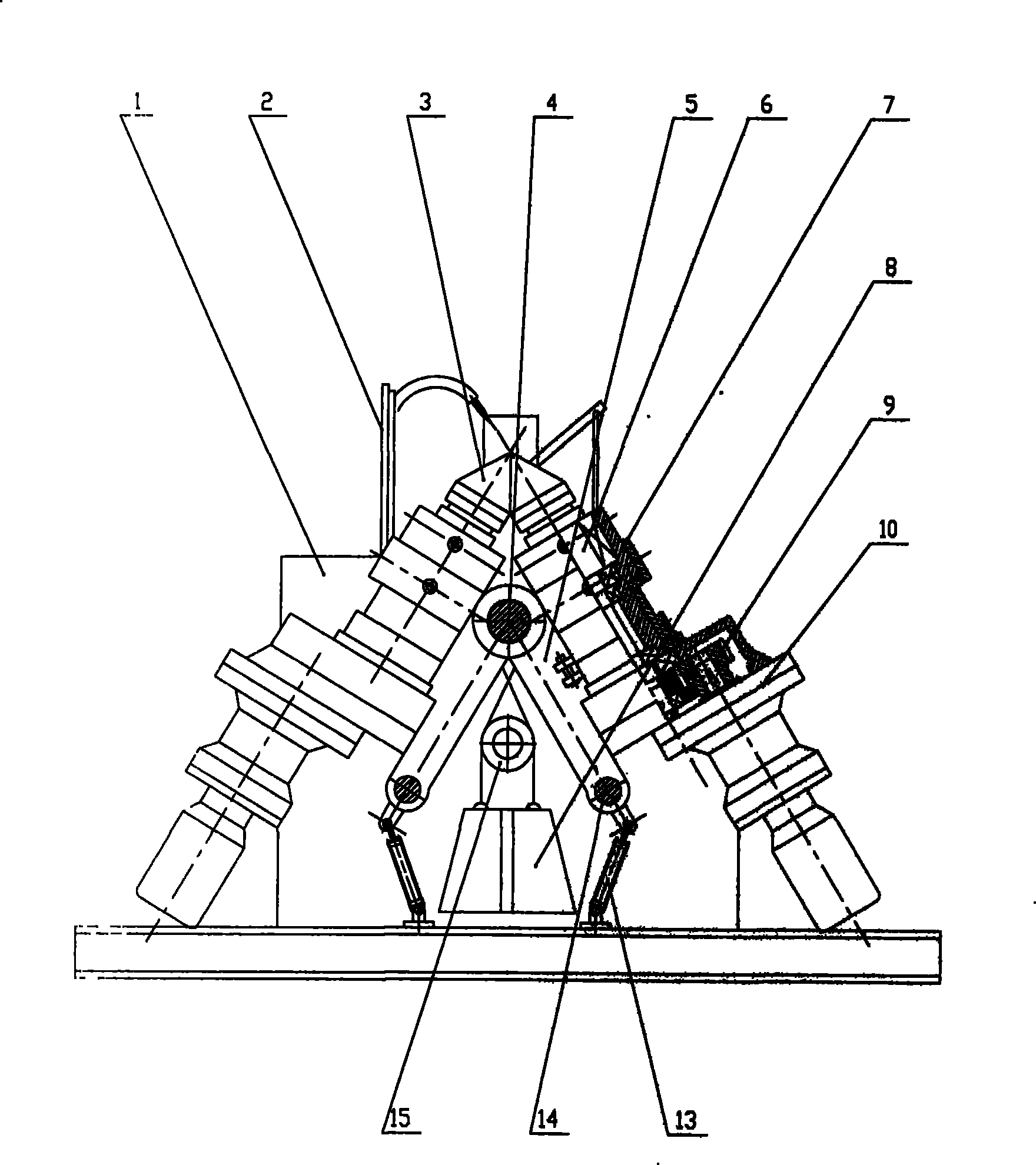
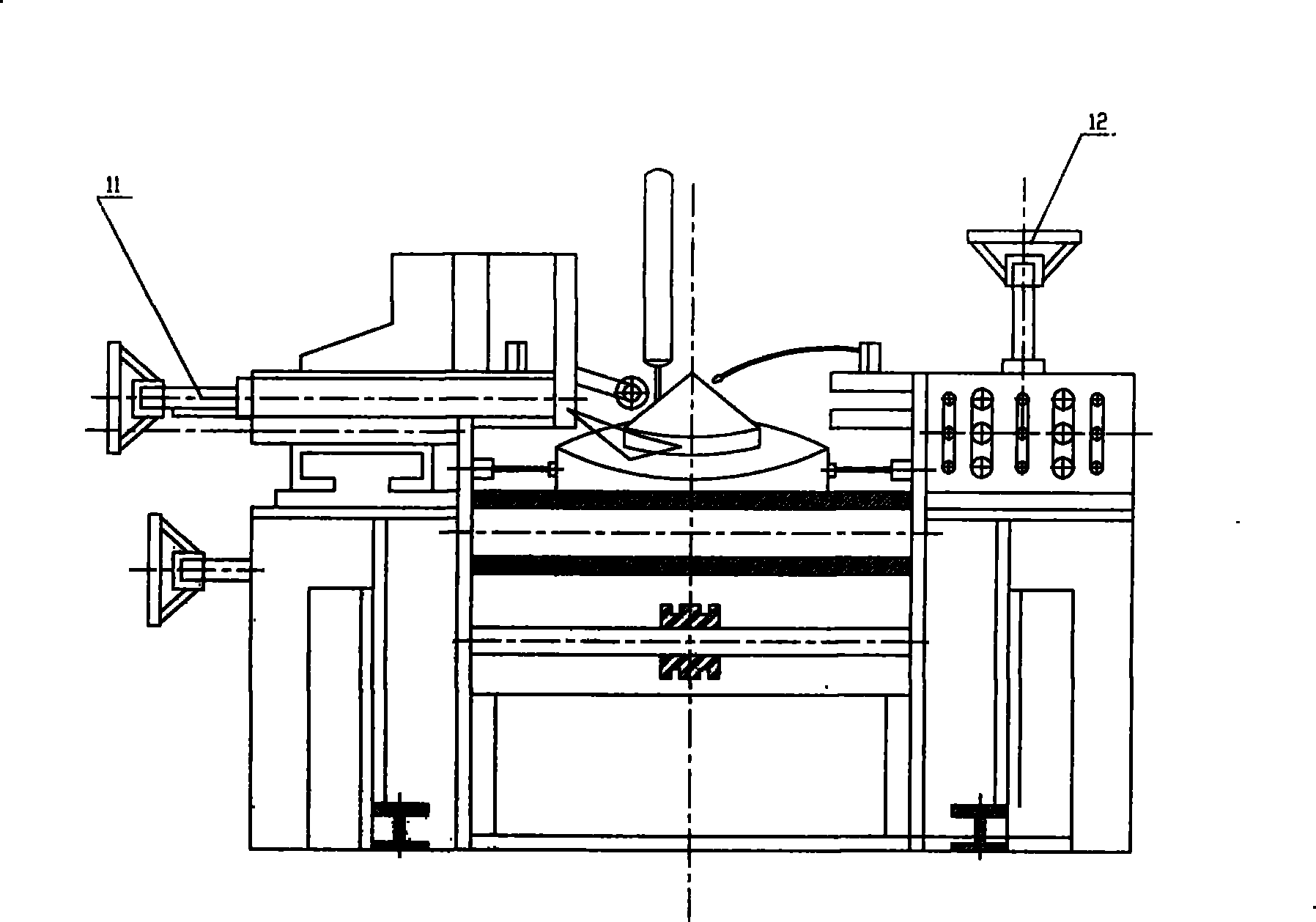
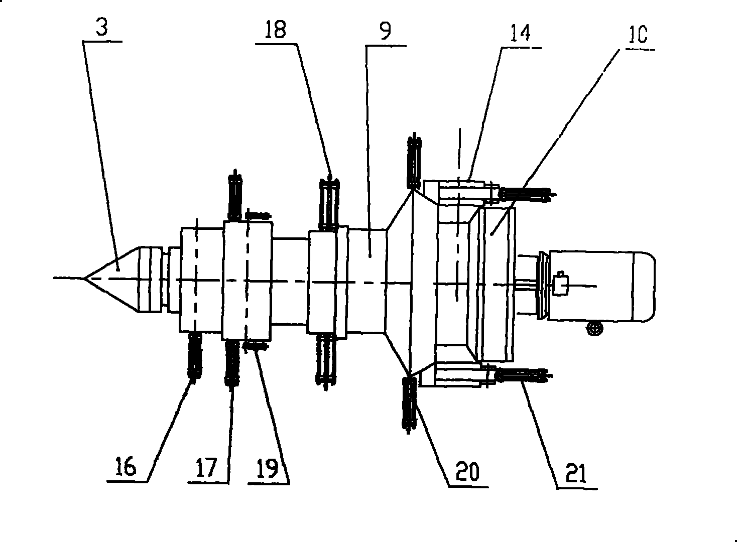
[0018] Referring to the accompanying drawings, the spiral blade rolling mill includes a frame 1 symmetrically arranged at both ends. The frame 1 is welded by H steel and angle steel to form a frame, supplemented by steel plates, and a fixed shaft 4 is horizontally arranged at both ends of the frame 1. 4 The supporting seat 5 is symmetrically hinged in the middle part, and the lower end of the supporting seat 5 is provided with an angle adjustment device. The angle adjusting device includes a floating shaft 14 inserted in the lower end of the supporting seat 5. In the installation hole of the floating shaft on the top, the axial ends of the floating shaft 14 are limited, and the lower end of the support seat 5 is hinged with a roll angle adjustment oil cylinder 13, and the other end of the roll angle adjustment oil cylinder 13 is hinged at the bottom of the frame 1. The angle adjustment oil cylinder 13 drives the support seat 5 to rotate around the fixed shaft 4, thereby driving...


PUM


Abstract

The invention discloses a helical blade rolling mill which comprises a stand, and two ends of the stand are symmetrically arranged; a fixed shaft is horizontally arranged along two ends of the stand, a support seat is symmetrically hinged at the approximately middle part of the fixed shaft, an angle adjusting device is arranged at the lower end of the support seat, and axial moving devices are symmetrically arranged along two sides of the support seat; a sliding seat which can slide up and down along the support seat is arranged at the outer side of the support seat, a main shaft driven by a power driving mechanism is arranged in the sliding seat, and tapered rollers are arranged at the upper end of the main shaft; and feeding devices and discharging devices are oppositely arranged at twosides of the tapered rollers. In the invention, as two rollers are supported on the same fixed shaft by the support seat, the central axial lines of the two rollers can be ensured to be coplanar as long as two sliding seat mounting holes on the support seat are ensured to be coaxial; as the helical blade rolling mill adopts the structure, the two sliding seat mounting holes are very easy to be coaxial, and the central axial lines of the two rollers have simple planar structure and are convenient for aligning; and the support seat is hinged on the fixed shaft, thereby having good adjusting stability.

Description

technical field [0001] The invention belongs to the technical field of mechanical rolling, and in particular relates to a spiral blade rolling mill. Background technique [0002] At present, the domestic spiral blade rolling mill adopts foreign technology. A pair of tapered rollers roll the strip material to change the cross section and elongate the longitudinal direction proportionally to form the spiral curved surface of the spiral blade. Here, the rolling gap is the key to rolling blades, because the thickness of the blade, the inner and outer diameter of the spiral and the pitch are different, the rolling gap is also different. Therefore, it is more complicated to adjust the rolling gap of the blades. It needs to comprehensively adjust the angle, misalignment, axial movement and relative position of the strip and the rollers. There are two methods for this adjustment, one is internal adjustment, that is, direct adjustment Adjust the position of the main shaft of the rol...

Claims


Application Information

Patent Timeline
Patent Type & Authority Patents(China)
IPC IPC(8): B21B1/00
Inventor 吴兴矿谢俊德
Owner SHANDONG YUANYOU HEAVY IND SCI & TECH
Why Eureka
Try Eureka