Permanent magnet type DC motor assembly

A technology for motors and components, applied in the direction of electric components, magnetic circuit rotating parts, electrical components, etc., to achieve the effect of enhanced meshing

Inactive Publication Date: 2009-09-02
DAEWOO ELECTRONICS CO LTD
View PDF0 Cites 1 Cited by
  • Summary
  • Abstract
  • Description
  • Claims
  • Application Information

AI Technical Summary

Problems solved by technology

In addition, there is also the disadvantage of leakage flux due to the deviation of the permanent magnet 30 from the rotor core 20

Method used


Image

  • Permanent magnet type DC motor assembly
  • Permanent magnet type DC motor assembly
  • Permanent magnet type DC motor assembly

Examples


Embodiment Construction

[0020] Hereinafter, preferred embodiments of the present invention will be described in detail with reference to the accompanying drawings.

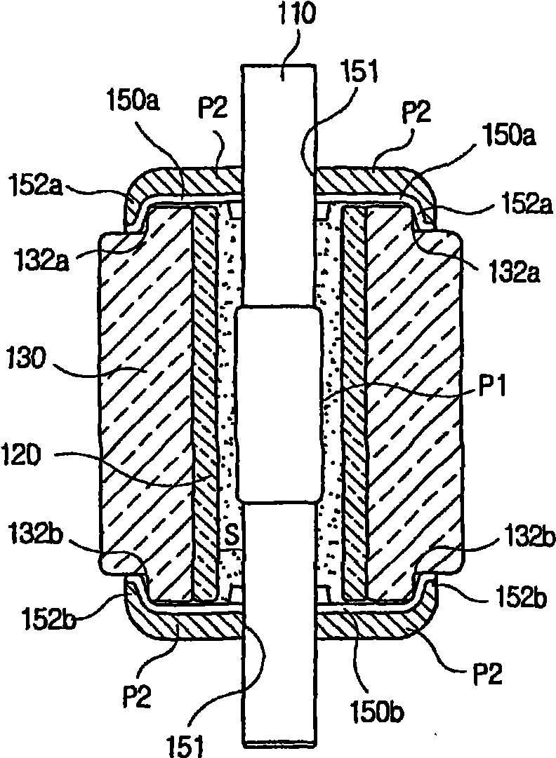
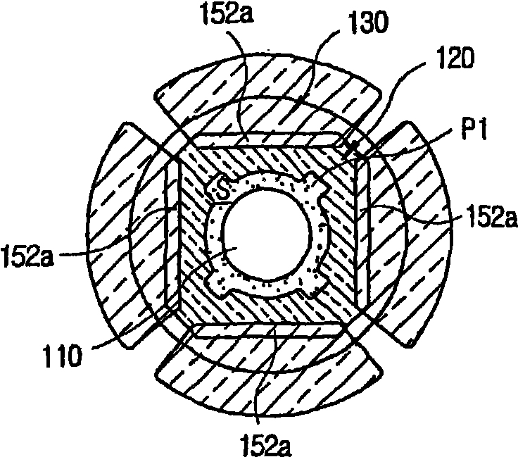
[0021] figure 2 and image 3 A cross-sectional view and a plan view of a DC motor assembly according to a preferred embodiment of the present invention are shown, respectively.

[0022] refer to figure 2 and image 3 , the DC motor assembly includes a rotary shaft 110 for performing rotary motion, a cylindrical rotor core 120 surrounding the rotary shaft 110, a plurality of magnets 130 attached and arranged on the outer periphery of the rotor core 120, and at the same time on the rotor core A predetermined distance is maintained between the magnet 120 and the magnet 130 . The DC motor assembly also includes upper and lower cover plates 150a and 150b as fixing members for fixedly engaging the magnet 130 and the rotor core 120 with the rotary shaft 110 in a more reliable manner.

[0023] The rotation shaft 110 is disposed substantia...


PUM


Abstract

A DC motor assembly includes a rotary shaft, a rotor core surrounding the rotary shaft while maintaining a specific gap from each other, a plurality of magnets arranged on an periphery surface of the rotor core, and a fixing member for fixedly engaging the magnets and the rotor core with the rotary shaft. The fixing member includes a pair of cap plates which are fixed around the rotary shaft at an upper end part and a lower end part of both of the rotor core and the magnets.

Description

technical field [0001] The present invention relates to a permanent magnet type DC motor assembly; and more particularly, the present invention relates to a permanent magnet type DC motor assembly provided with a fixing member for engaging a magnet and a rotor core with a rotating shaft. Background technique [0002] DC motor components are mainly used to drive electrical appliances in household or industrial fields. Recently, various motor assemblies capable of high-speed rotation have been developed, thereby increasing task execution speed or response speed to user operations. [0003] In particular, a brushless DC motor has been developed as a motor assembly for performing high-speed rotation. [0004] In such a high-speed rotatable DC motor, a rotor and a magnet are engaged with a rotating shaft, and are rotated by the rotation of the rotating shaft. At this point, if the rotor and magnets are not properly engaged with each other, there is a risk that the rotor and mag...

Claims


Application Information

Patent Timeline
Patent Type & Authority Applications(China)
IPC IPC(8): H02K1/27
CPCH02K1/278H02K1/27
Inventor 刘昌范
Owner DAEWOO ELECTRONICS CO LTD
Why Eureka
Try Eureka