Element which generates a magnetic field

A component and magnetic field technology, applied in the field of components that generate magnetic fields, can solve the problems of insufficient absorption force and tightening torque, unsuitable nuts, etc., and achieve the effect of saving cost and production time

Inactive Publication Date: 2009-08-26
CONTINENTAL AUTOMOTIVE GMBH
View PDF1 Cites 1 Cited by
  • Summary
  • Abstract
  • Description
  • Claims
  • Application Information

AI Technical Summary

Problems solved by technology

In order to generate a well-measurable magnetic field in the sensor, on the one hand the rotating magnet must be as large as possible and generate a sufficient field strength, and on the other hand all magnets are made of very brittle materials, so that the nut is very fragile. Suitable as a component for fastening the compressor wheel to the turbine shaft, since the brittle magnetic material absorbs the forces and fastenings that occur when fastening the compressor wheel to the turbine shaft only to a limited extent or not sufficiently torque

Method used


Image

  • Element which generates a magnetic field
  • Element which generates a magnetic field
  • Element which generates a magnetic field

Examples


Embodiment Construction

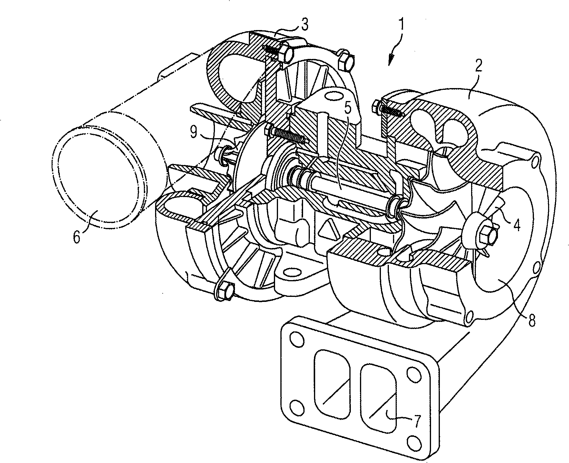
[0025] figure 1 An exhaust gas turbocharger 1 with a turbine 2 and a compressor 3 is shown. The compressor wheel 9 is rotatably mounted in the compressor 3 and connected to the turbine shaft 5 . The turbine shaft 5 is also mounted rotatably and is connected at its other end to the turbine wheel 4 . The combination of the compressor wheel 9 , the turbine shaft 5 and the turbine wheel 4 is also referred to as a rotor assembly. Hot exhaust gases from the internal combustion engine, not shown here, pass through the turbine inlet 7 into the turbine 2 , wherein the turbine wheel 4 is in rotation. The exhaust gas flow leaves the turbine 2 through the turbine outlet 8 . The turbine wheel 4 is connected to a compressor wheel 9 via a turbine shaft 5 . The turbine 2 thus drives the compressor 3 . In the compressor 3 , air is sucked in via the air inlet 16 , subsequently compressed in the compressor 3 and delivered to the internal combustion engine via the air outlet 6 .

[0026] ...


PUM


Abstract

The invention relates to an element which generates a magnetic field for fastening a compressor wheel to a turboshaft of an exhaust-gas turbocharger, having a basic body and a thread. In order to specify an element which generates a magnetic field for fastening a compressor wheel to a turboshaft, which element generates as high a magnetic field strength as possible and nevertheless can absorb without damage the forces and the tightening torques which occur during fastening of the compressor wheel to the turboshaft, the entire basic body comprises a magnetic material and a sleeve is arranged in the basic body, which sleeve comprises a non-magnetic material and has the thread which can be screwed to a mating thread of the turboshaft.

Description

technical field [0001] The invention relates to a component for generating a magnetic field for fastening a compressor wheel on a turbine shaft of an exhaust gas turbocharger, which component has a base body and a thread. Background technique [0002] The power produced by an internal combustion engine depends on the amount of air and fuel delivered to the engine. In order to increase the power, it is necessary to increase the amount of combustion air and fuel delivered to the internal combustion engine. In non-supercharged engines with internal combustion engines, the increase in power is achieved by increasing the working volume of the cylinders or by increasing the rotational speed. However, enlarging the cylinder displacement in principle leads to a considerable increase in size and thus to a more expensive internal combustion engine. However, an increase in rotational speed brings with it significant problems and disadvantages, especially in the case of larger interna...

Claims


Application Information

Patent Timeline
IPC IPC(8): F02B39/16G01P3/44F01D17/06
CPCF05D2220/40F05B2220/40F02B39/16F01D17/06G01P3/44G01P3/487
Inventor 约翰内斯·安特斯特凡·海因里希安德烈亚斯·奥特丹尼·舍德利希
Owner CONTINENTAL AUTOMOTIVE GMBH
Why Eureka
Try Eureka