Rapidly mounted hinge wing for furniture

A technology of flaps and hinges, applied in the field of hinged flaps, can solve problems such as excessive size

Inactive Publication Date: 2009-08-19
AGOSTINO FERRAR SPA
View PDF1 Cites 2 Cited by
  • Summary
  • Abstract
  • Description
  • Claims
  • Application Information

AI Technical Summary

Problems solved by technology

The problem is particularly acute given that the hinge flaps may be applied to different types and degrees of firmness of materials such as particleboard and solid wood: fastening mechanisms exist for fastening the cup and are sufficient for softer materials when fastened on Risk of excessive force required on harder materials
On the other hand, mechanisms exist that can achieve adequate fixation with acceptable forces on hard materials that cannot provide sufficient strength assurance for softer materials

Method used


Image

  • Rapidly mounted hinge wing for furniture
  • Rapidly mounted hinge wing for furniture
  • Rapidly mounted hinge wing for furniture

Examples


Embodiment Construction

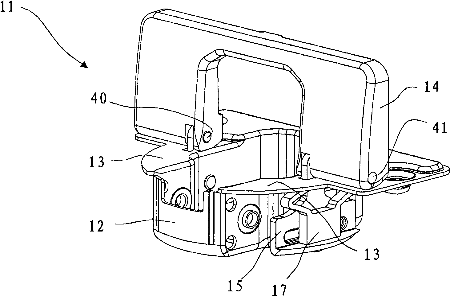
[0032] With reference to the accompanying drawings, figure 1 Hinge tabs used in hinges for connecting furniture parts are shown. The complete hinge is not shown in this figure, said hinge is easily conceivable by a person skilled in the art and may comprise a second hinge flap fixable to a second furniture part according to known teachings.

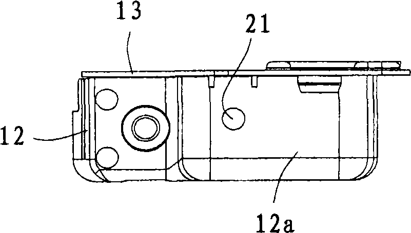
[0033] The hinge flap 11 comprises a hole 50 for insertion into a furniture part (in image 3 and 4 A cup (or box) 12 in ), the furniture part such as a flap or door.

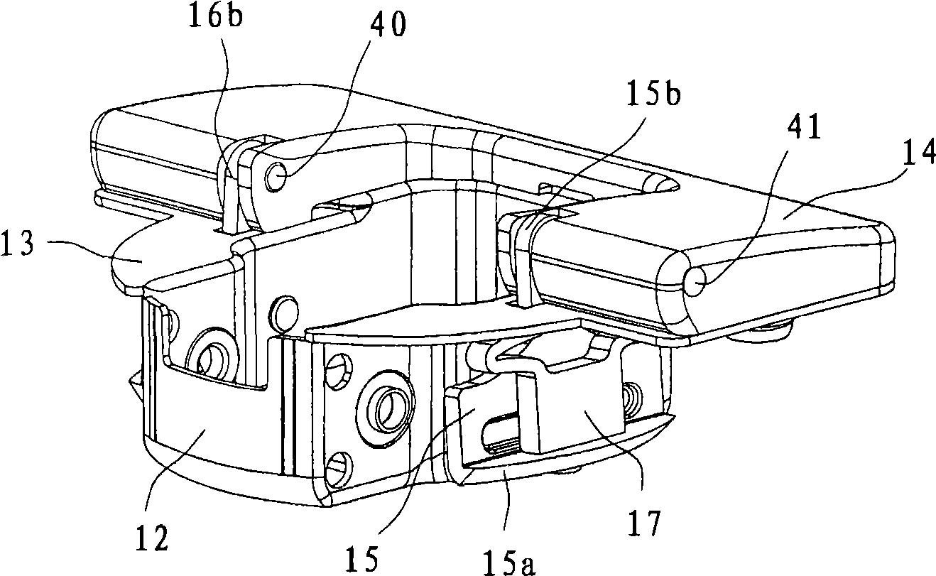
[0034] The hinge flaps include a pair of splayable teeth 15, 16 (also in image 3 and 4 ), the pair of teeth are arranged on the exterior of the cup 12 on opposite sides of the cup.

[0035] Teeth 15 ( Figure 9 and 10 ) is generally L-shaped and includes a hook portion 15a for pressing against the side wall of the receiving hole 50 of the cup for fixing to a furniture part. The tooth also includes an upper arm 15b provided for passing through a pivot 41 ( figure...


PUM


Abstract

A hinge wing comprises a cup (12) intended for being fixed in a hole (50) of a furniture component, the wing being provided with a pair of expandable teeth (15, 16) arranged on opposite sides of the cup, said teeth being fixed on an eccentric lever (14) of the wing, by rotating which the teeth are moved in an opposite direction to the direction of insertion of the cup into the respective receiving hole, the wing comprising for each tooth a cam that, upon rotation of the eccentric lever, causes the respective tooth to expand against a side wall of the receiving hole of the cup to fix the cup to the furniture component. Each cam is formed with a cam element (19, 20) of yieldable material interposed between a side wall of the cup (12) and the respective tooth (15, 16).

Description

technical field [0001] The present invention relates to an innovative hinge wing that can be mounted on a furniture part without the use of tools. Background technique [0002] The hardware market for furniture has undergone innovations which have enabled fast and stable fastening of hardware elements to wooden panels. In particular, in the case of furniture for the "DIY (Do It Yourself)" market, there is a growing demand for fastening systems called "Tool-less Mounting (TLM)", which do not require the aid of any type of tool (such as a screwdriver or hammer) to ensure that it is firmly fixed. [0003] The TLM system has been used in particular to secure cup-shaped fins (ie those provided with a "box") in suitable holes typically formed in furniture walls. [0004] However, the currently known products do have inherent manufacturing difficulties, mainly because the energy required to achieve the fixation of the cup must be provided by means of minimal movement of movable p...

Claims


Application Information

Patent Timeline
Patent Type & Authority Applications(China)
IPC IPC(8): E05D5/08
CPCE05Y2201/638E05Y2900/20E05D11/0054E05Y2201/626E05Y2600/52E05D5/08E05D7/125
Inventor A·费拉里
Owner AGOSTINO FERRAR SPA
Why Eureka
Try Eureka