
Double-frequency antenna

A dual-band antenna, low-frequency technology, which is applied to antennas, antenna supports/installation devices, and devices that enable antennas to work in different frequency bands at the same time, which can solve the problems of narrow impedance matching bandwidth and incompatibility.

Inactive Publication Date: 2009-08-05
QUANTA COMPUTER INC
View PDF1 Cites 13 Cited by
  • Summary
  • Abstract
  • Description
  • Claims
  • Application Information

AI Technical Summary

Problems solved by technology

However, the impedance matching bandwidth of the dual-band antenna 11 in the high-frequency band is relatively narrow, which cannot meet the application requirements

Method used


Image

  • Double-frequency antenna
  • Double-frequency antenna
  • Double-frequency antenna

Examples


Embodiment Construction

[0057] The aforementioned and other technical contents, features and effects of the present invention will be clearly presented in the following detailed description of two preferred embodiments with reference to the accompanying drawings.

[0058] Before the present invention is described in detail, it should be noted that in the following description, similar elements are denoted by the same reference numerals.

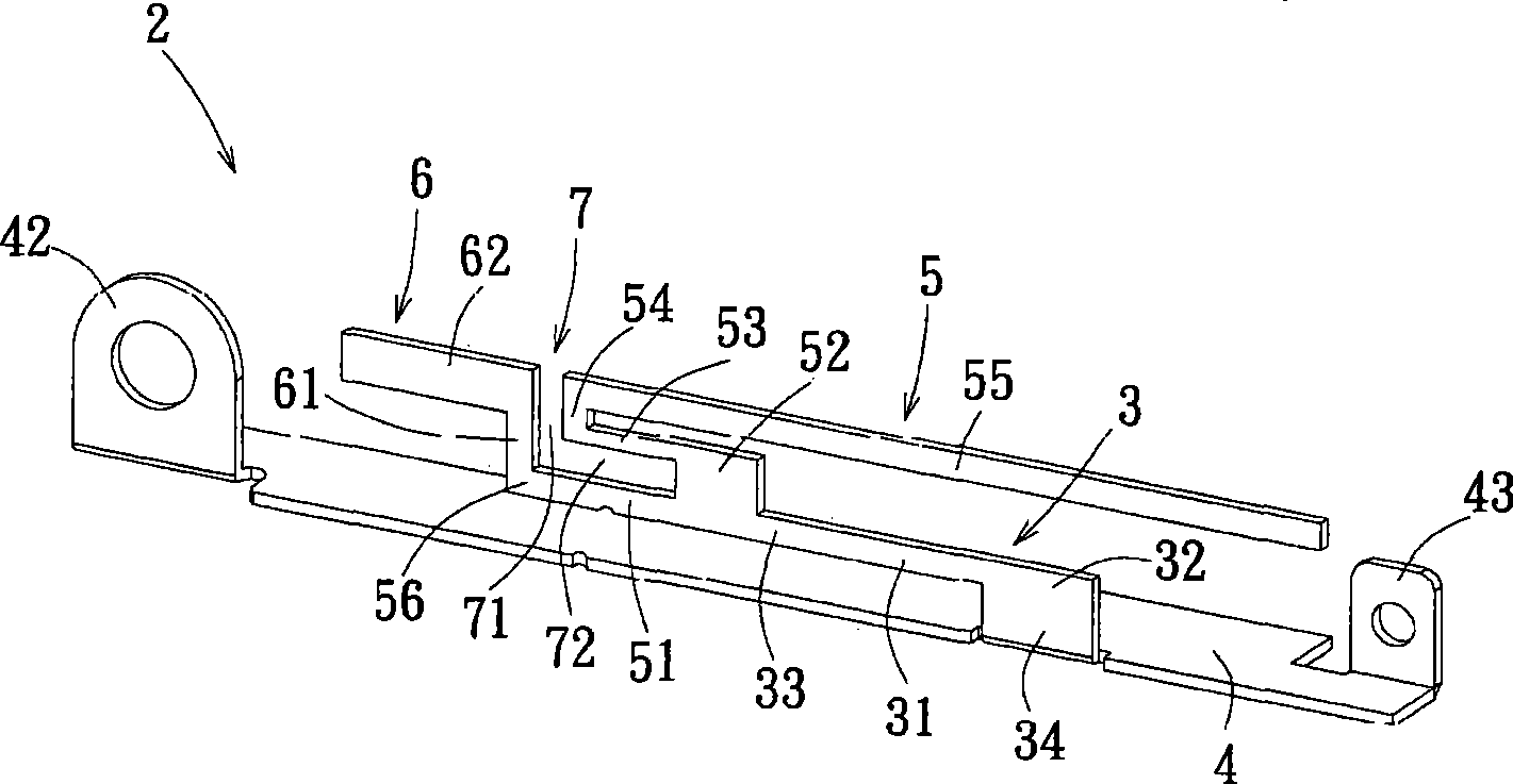
[0059] refer to figure 2 , image 3 and Figure 4 , the first preferred embodiment of the dual-band antenna 2 of the present invention is set in the notebook computer 9, the set position can be position 91 or position 92, and its main structure includes a ground section 3, a strip-shaped ground part 4 , a low-frequency radiation part 5 and a high-frequency radiation part 6 .

[0060] The grounding section 3 is generally in an inverted L shape and includes a horizontal section 31 , a vertical section 32 connected to the horizontal section 31 , a connecting end 33...


PUM


Abstract

The invention relates to a dual-frequency antenna, which comprises a grounding segment, a low-frequency radiation part and a high-frequency radiation part. The grounding segment comprises a connecting end and a grounding end opposite to the connecting end. The low-frequency radiation part is connected with the connecting end of the grounding segment so as to work at the low-frequency band (2400 MHz to 2500 MHz), and comprises a signal feed end. The high-frequency radiation part works at the high-frequency band (4900MHz to 5900MHz), extends outwards from the signal feed end of the low-frequency radiation part, and defines a slot opening together with the low-frequency radiation part. The slot opening is coupled with the low-frequency radiation part and the high-frequency radiation part, thereby increasing the working bandwidth of the antenna at the high-frequency band.

Description

technical field [0001] The present invention relates to a dual-frequency antenna, and in particular to a dual-frequency antenna with a PIFA structure. Background technique [0002] At present, the built-in antenna of notebook computer used in WLAN (IEEE 802.11a / b / g) mainly adopts the antenna structure of PIFA (Planar Inverted F Antenna, planar inverted F antenna), and the signal feed-in end excites the high and low frequency respectively. The resonant cavity can achieve a dual-band effect, but due to space constraints, its bandwidth often has the disadvantage of insufficient. [0003] refer to figure 1 , which shows the PIFA type dual-frequency antenna 11 disclosed in US Pat. The ground portion 15 of the ground 10 . The high-frequency radiation part 12 extends horizontally from the end of the signal feed-in part 14 to the left to work in the 4840MHz-5800MHz frequency band; the low-frequency radiation part 13 extends horizontally from the end of the signal feed-in part 14 ...

Claims


Application Information

Patent Timeline
Patent Type & Authority Applications(China)
IPC IPC(8): H01Q1/22H01Q1/38H01Q5/00H01Q5/10H01Q5/20H01Q5/364
Inventor 蔡调兴郭肇强吴正雄
Owner QUANTA COMPUTER INC
Learn More