


Quick Research
Generate reliable direction feasibility study reports for your R&D in just a few steps.

Technical Q&A
Discover and master advanced knowledge NOW. Basics, ideas, possibilities, all at once.

Find Solutions
As an expert in R&D theories, this can generate solutions to your technical problems instantly.

Evaluate Feasibility
Analyze your overall solution with one click, know your potential R&D risks in advance.

Monitor Landscape
Get weekly tech updates, stay abreast of the latest tech innovations and key insights.
Electric railway alternating current feeding system
An electrified railway, AC feeding technology, applied in power lines, vehicle components, transportation and packaging, etc., can solve the problems of inability to pull through single-phase AC, difficulties in the public interest of trains, and difficult to achieve, to simplify the control of trams, The effect of improving riding mood and reducing load
- Summary
- Abstract
- Description
- Claims
- Application Information
AI Technical Summary
Problems solved by technology
Method used
Image

Examples
no. 1 Embodiment approach
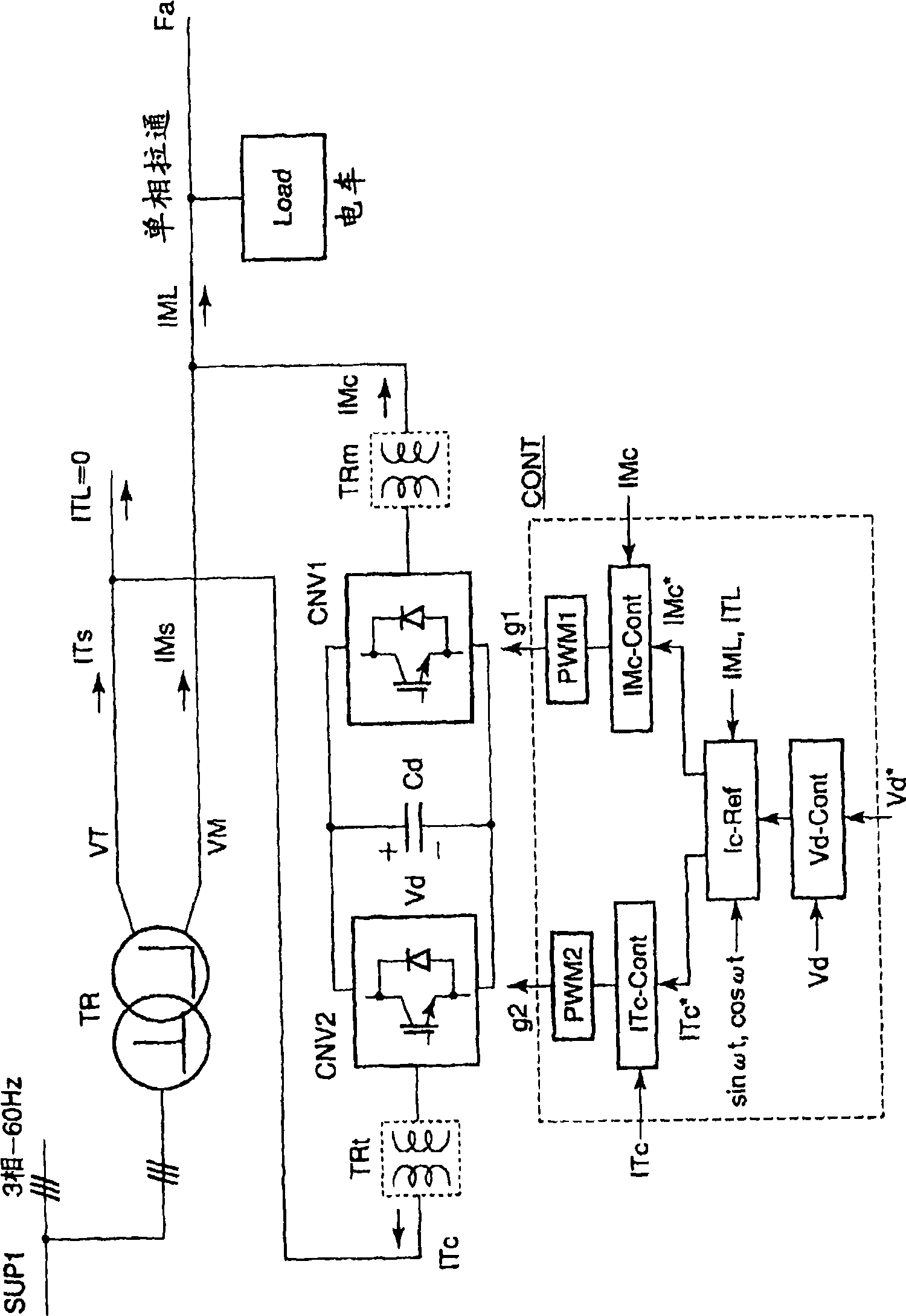
[0112] figure 2 It is a block diagram showing the first embodiment of the electric railway AC power feeding system of the present invention. In the figure, SUP1 represents a three-phase AC power supply, TR represents a Scott connection transformer, Fa represents a single-phase AC feeder, Load represents a tram load, TRm and TRt represent a single-phase transformer, and CNV1 and CNV2 represent voltage-type self-excited power conversion Cd represents a DC smoothing capacitor, and CONT1 represents a control unit that balances the above-mentioned two-phase unbalanced compensation currents (compensation current detection values) IMc, ITc outputted through power converters CNV1, CNV2 and single-phase transformers TRm, TRt. Compensation currents IMc and ITc are obtained by disposing current detectors in, for example, Hall CTs not shown in the figure. figure 2 The arrow position of can be detected.
[0113] The Scott connection transformer TR transforms the three-phase AC power so...
no. 2 Embodiment approach
[0163] Figure 10 It is a block diagram showing an AC power feeding system for an electrified railway according to a second embodiment of the present invention.
[0164]In the figure, SUP1 represents a three-phase AC power supply, TR represents a Scott connection transformer, Fa represents a single-phase AC feeder, Load represents a tram load, TRm and TRt represent a single-phase transformer, and CNV1 and CNV2 represent voltage-type self-excited power conversion Cd represents a DC smoothing capacitor, Lf and Cf represent reactors and capacitors constituting an LC filter, and CONT1 represents a control unit for compensating currents IMc and ITc output from the above-mentioned power converters CNV1 and CNV2.
[0165] The Scott connection transformer TR transforms the three-phase AC power sources Vu, Vv, Vw into two-phase AC voltages VM, VT, and the two-phase voltages VM and VT have a phase difference of 90°.
[0166] The M block output is connected to the single-phase AC feeder...
no. 3 Embodiment approach
[0199] Figure 12 It is a block diagram showing a third embodiment of a control unit for compensation currents IMc, ITc outputted from the first and second self-excited power converters CNV1, CNV2 in the AC feed system of the present invention.
[0200] In the figure, Kff represents a proportional element, C1~C3 represent a comparator, Gv(S) represents a voltage control compensation circuit, M1, M2 represent a multiplier, AD1~AD5 represent an adder / subtractor, Gi1(S), Gi2(S) Indicates the current control compensation circuit, PWM1 and PWM2 are pulse width modulation control circuits.
[0201] The power PL of the single-phase load Load fluctuates at twice the frequency f1 of the AC feeder line. The detected value of the load power PL is time-averaged to obtain the average value PL(av) of the load power. Then, through the proportional element Kff, the effective current peak value command Ismff of the forward compensation proportional to the above-mentioned load power average v...
PUM
 Abstract
Description
Claims
Application Information
 - R&D Engineer
- R&D Manager
- IP Professional
- Industry Leading Data Capabilities
- Powerful AI technology
- Patent DNA Extraction
Browse by: Latest US Patents, China's latest patents, Technical Efficacy Thesaurus, Application Domain, Technology Topic, Popular Technical Reports.
© 2024 PatSnap. All rights reserved.Legal|Privacy policy|Modern Slavery Act Transparency Statement|Sitemap|About US| Contact US: help@patsnap.com