Labor-saving type manual nailing gun
A labor-saving, nail gun technology, used in nailing tools, manufacturing tools, etc., can solve the problems of poor work efficiency and labor, and achieve the effect of improving work efficiency and accurately changing positions
Inactive Publication Date: 2010-08-25
APEX MFG
View PDF0 Cites 0 Cited by
- Summary
- Abstract
- Description
- Claims
- Application Information
AI Technical Summary
Problems solved by technology
The technical problem to be solved by the labor-saving manual nail gun of the present invention is that the fulcrum of the actuating mechanism of the existing nail gun is fixed, so that the length of the force arm is fixed. The force of the object makes it necessary to exert a large force to drive the needle, which is not only laborious, but also makes the work efficiency worse
Method used
View moreImage
Smart ImageViewing Examples
Examples
Embodiment Construction
Login to View More PUM
 Abstract
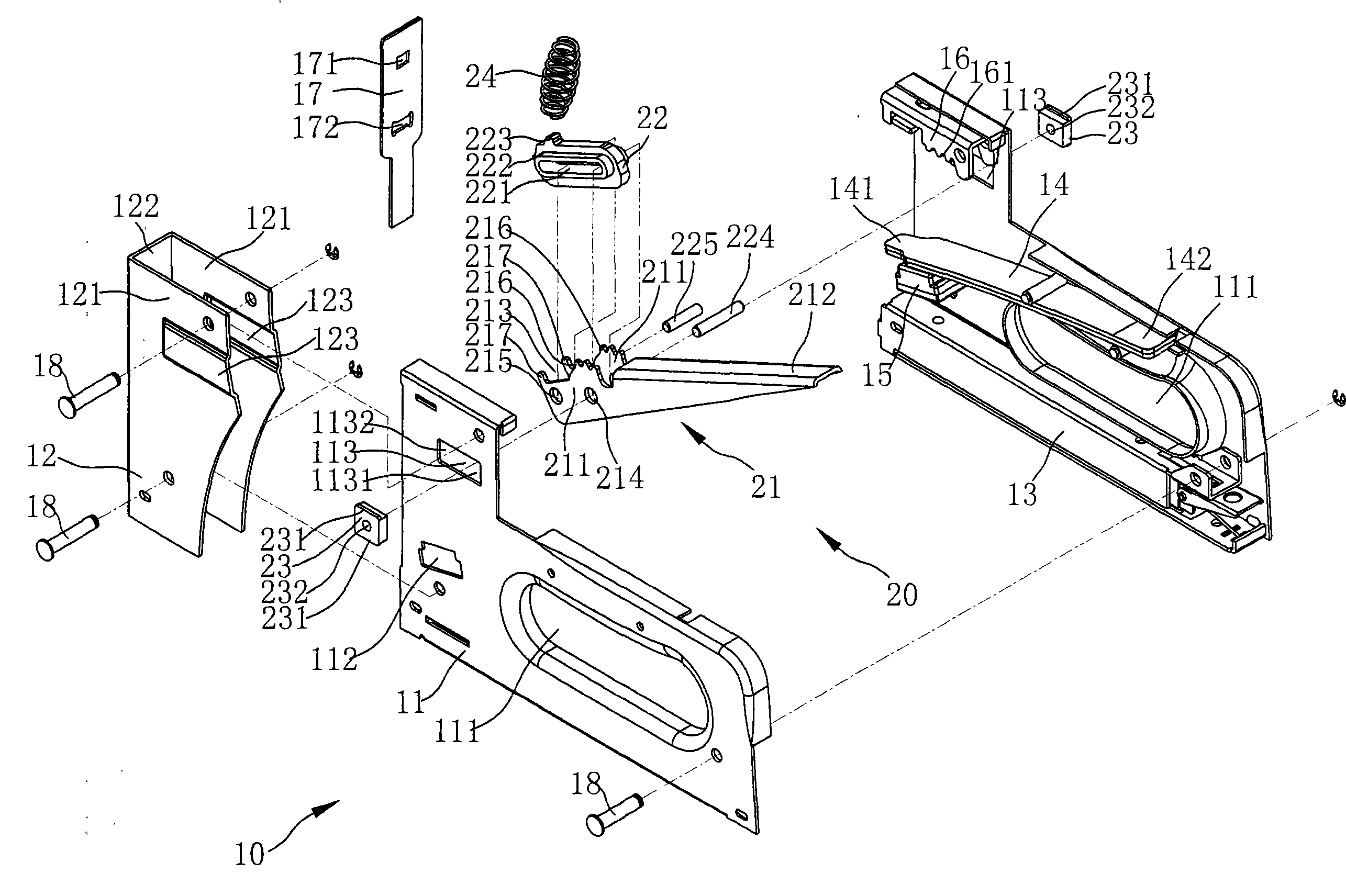
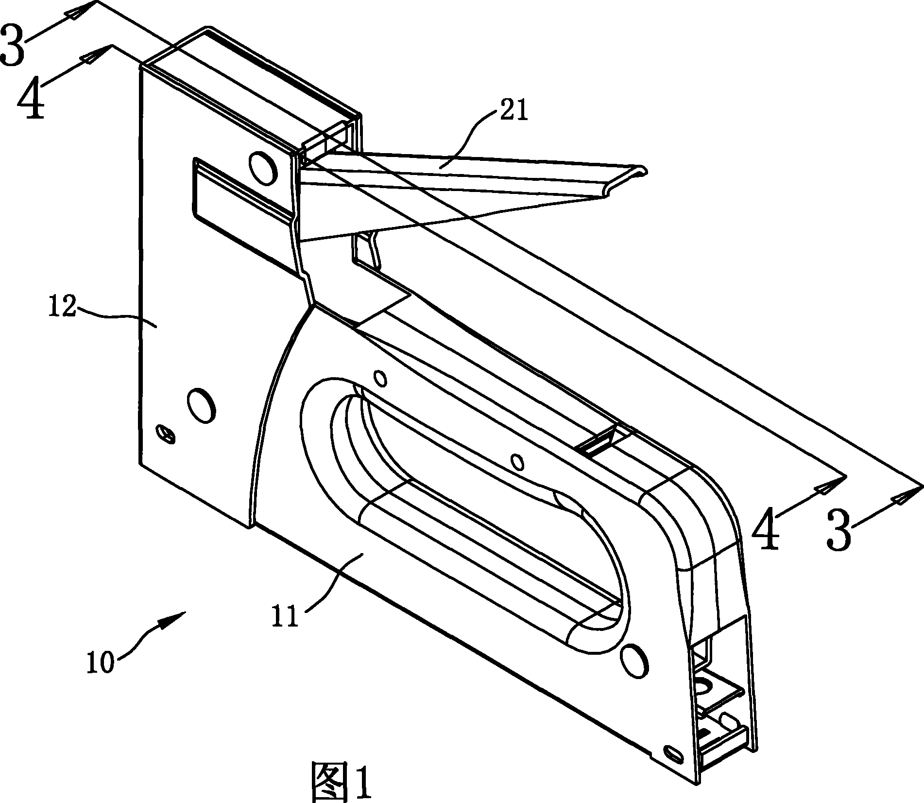
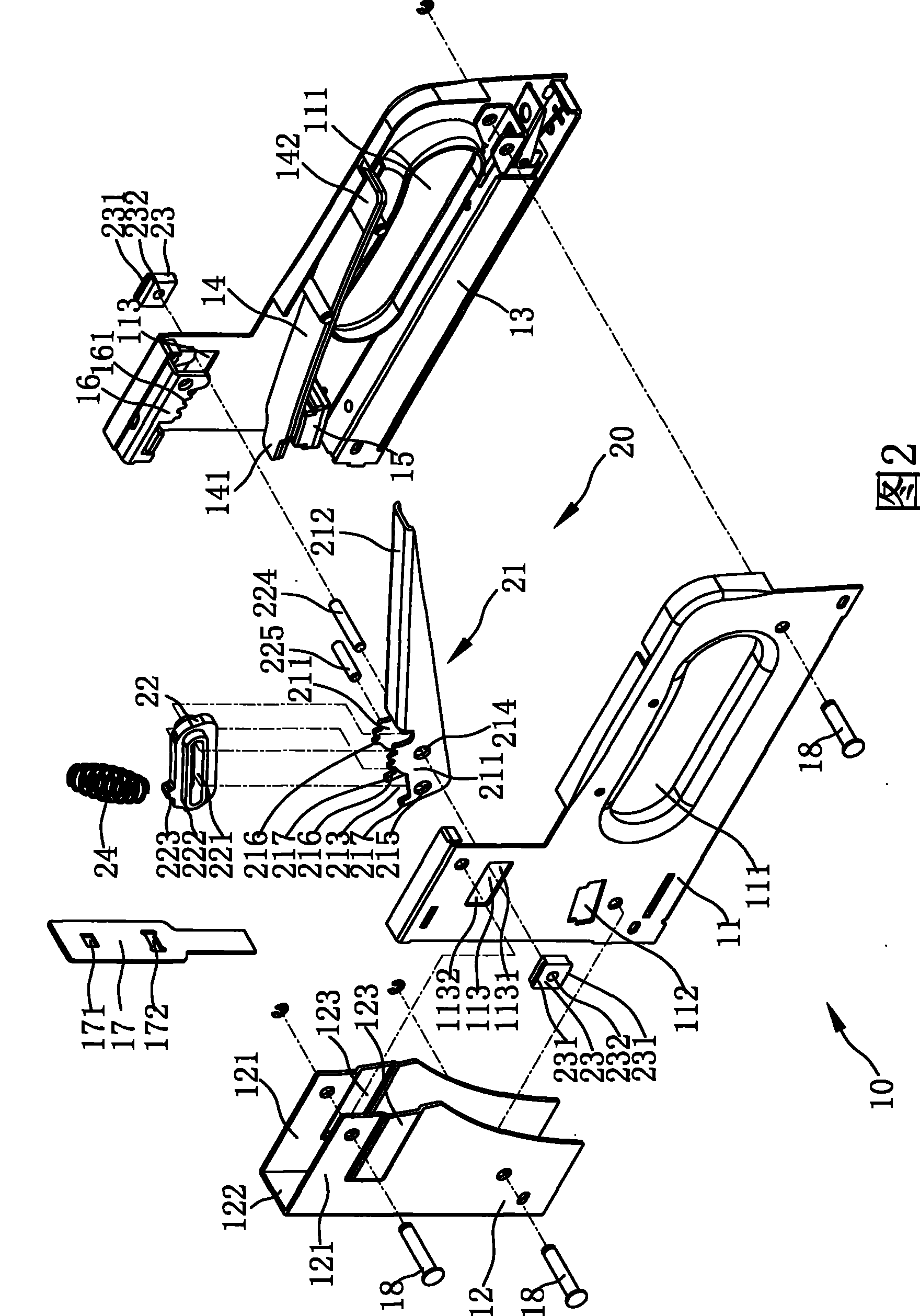
The invention relates to a labor-saving type manual nail gun which comprises a body coated with a labor-saving mechanism. The labor-saving mechanism comprises a pressing piece and a movable piece, wherein one end of the pressing piece is a pressing part, the other end of the pressing piece is provided with a connecting piece, a limited part and a braking part, and the braking part is meshed with a propping piece; and the movable piece is limited on the pressing piece by the connecting piece and the limited part. Furthermore, the movable piece is provided with a movable groove and a linking part, the connecting piece and the limited part are arranged in the movable groove and respectively penetrate through the pressing part, wherein the connecting piece is limited to move in guiding grooves positioned on two lateral shells. Because the braking part is meshed with the body, the movable piece moves fast, and the connecting piece moves in the guiding groove, thereby a forcing arm is more and more longer, and a force resistant arm is more and more shorter when a nail is shot so as to cause the pressing force of an operator to be more and more less when the operator presses the pressingpart.
Description
Labor-saving manual nail gun technical field The invention relates to a manual nail gun, in particular to a labor-saving manual nail gun. Background technique Please refer to FIG. 9 , which is a schematic diagram of an existing manual nail gun. The actuating mechanism of the existing nail gun 90 has a nailing piece 91, two elastic members 92 and a pressing handle 93, and the pressing handle 93 of the actuating mechanism is fixed on the housing by means of a shaft rod 94. 95, and the actuating mechanism is based on the shaft 94 as a fulcrum, the fixed length of the pressing handle 93 is the distance from the shaft 94 to the pressing long tail end 96. The length of the force arm, and the distance from the shaft rod 94 to the reed hook 97 is the resistance arm. When the nail gun 90 hits the nail, the pressing handle 93 is pressed down more, because it needs to be applied. It is hard on the nails, so it needs to exert a greater force, and this nail gun 90 is indeed a laborio...
Claims
Login to View More Application Information
Patent Timeline
 Patent Type & Authority Patents(China)
IPC IPC(8): B25C1/02
Inventor 蔡富丞张碧宜胡志玮
Owner APEX MFG
Features
- R&D
- Intellectual Property
- Life Sciences
- Materials
- Tech Scout
- Unparalleled Data Quality
- Higher Quality Content
- 60% Fewer Hallucinations
Learn More Browse by: Latest US Patents, China's latest patents, Technical Efficacy Thesaurus, Application Domain, Technology Topic, Popular Technical Reports.
© 2025 PatSnap. All rights reserved.Legal|Privacy policy|Modern Slavery Act Transparency Statement|Sitemap|About US| Contact US: help@patsnap.com


