
Vapour-liquid distribution device

A distribution device and downflow technology, which is applied in the field of liquid-gas distribution device, can solve problems such as uneven liquid distribution and achieve good wetting efficiency

Active Publication Date: 2009-07-15
HALDOR TOPSOE AS
View PDF6 Cites 6 Cited by
  • Summary
  • Abstract
  • Description
  • Claims
  • Application Information

AI Technical Summary

Problems solved by technology

This causes uneven liquid distribution on the surface below the swash plate

Method used


Image

  • Vapour-liquid distribution device
  • Vapour-liquid distribution device
  • Vapour-liquid distribution device

Examples


Embodiment Construction

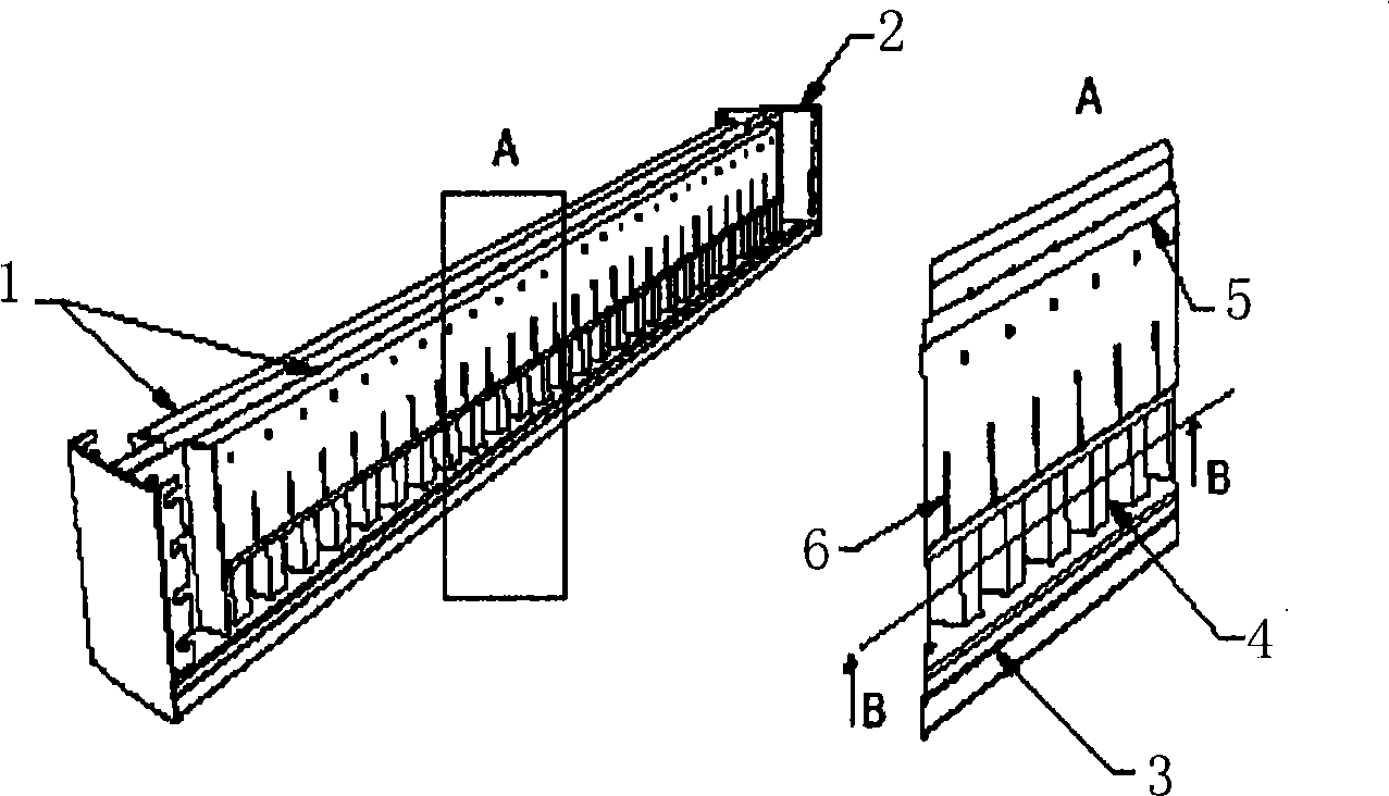
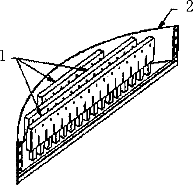
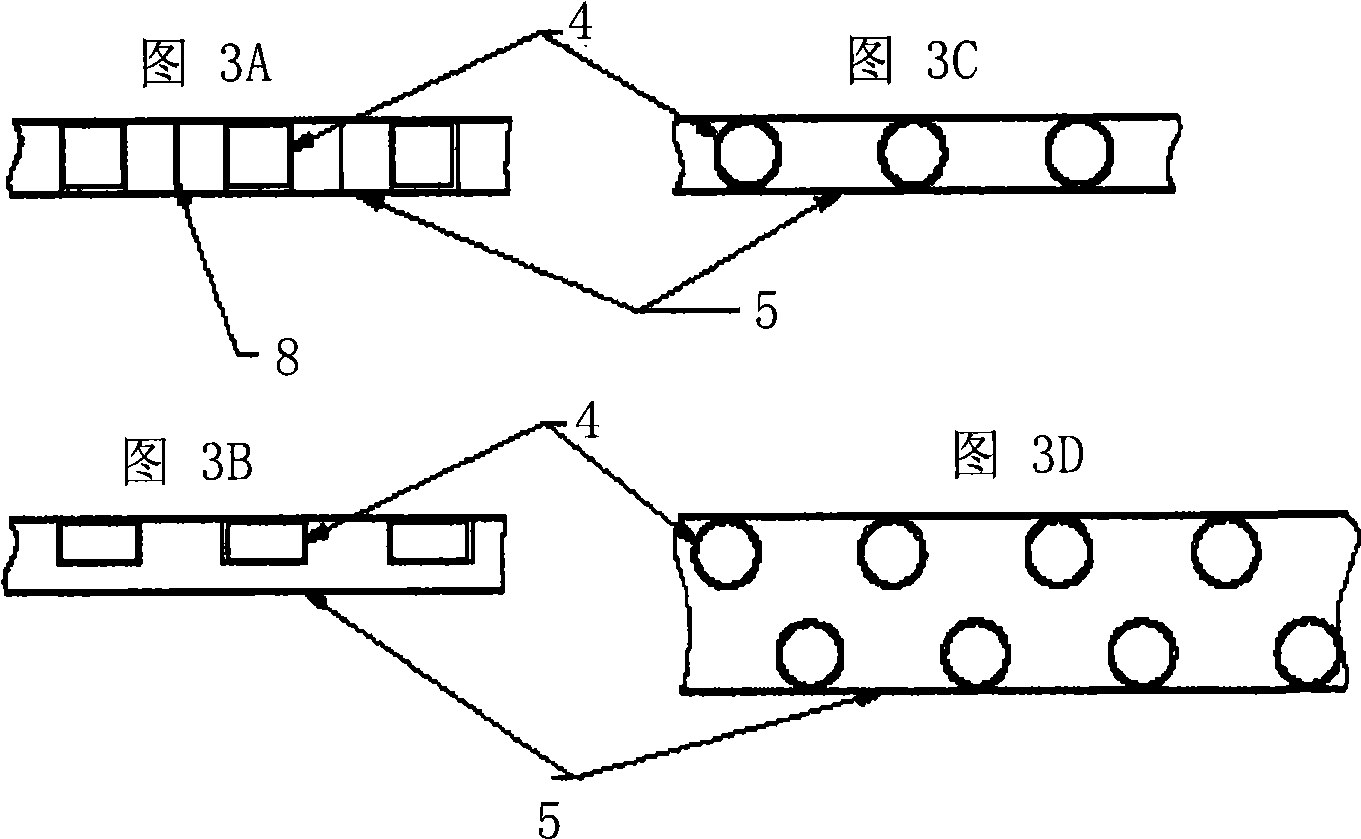
[0030] exist figure 1 and figure 2 The concept of a liquid-gas distribution design (called a self-supporting structure) is represented in . The device comprises one or several BOXVLTs extending from one side of the reactor inner wall to the other side of the reactor inner wall, with skirts 2 curved at a curvature corresponding to the curvature of the reactor inner wall (not shown) so as to be airtight Install. The long sides 7 of the self-supporting structure are linear and fit together with either another self-supporting structure (not shown) or a non-self-supporting tray plate equipped with one or several BOXVLTs (not shown). All connections are essentially leak-free. Each BOXVLT includes a common riser cap that covers 2 or more downcomers 4 . The downcomer 4 can vary in size, shape and pattern of arrangement (see image 3 example of). Each downcomer fits into a hole drilled in the base plate 3 . One or more vertical narrow slots 6 are cut in the side walls of the ri...


PUM


Abstract

A liquid-vapour distribution device for use in two-phase stream concurrent down-flow vessels comprising: a plurality of BOXVLTs fabricated in form of self-supporting structures (beams) and tray panels when installed forms a tray which will be essentially leak free at the junctions and between the tray and the vessel wall; said horizontal self-supporting structure consisting of a bottom plate being perforated with at least one row of apertures of equal size, wherein each aperture is fitted with an elongated down-flow channel (downcommer) being in form of a tube or any other geometric shape with the same geometrical cross sectional shape as the apertures in said beam and the down-flow channel is provided with an inlet for the concurrent two-phase stream, and wherein at least two of said down-flow channels are fitted with a common riser cap being attached to and along at least one wall portion of each down-flow channel and mounted over and spaced apart the inlet of the down-flow channel.

Description

technical field [0001] The present invention relates to a liquid-gas distribution device for a two-phase co-current downflow vessel. In particular, the present invention relates to liquid distribution apparatus in the form of a common manifold incorporating multiple gas risers, known as box gas risers (BOXVLTs), which improve liquid and gas Phase partitioning to achieve heat and compositional balance in catalytic reactions. This device is particularly useful in hydroprocessing reactors. Background technique [0002] Five designs of liquid dispensing devices are known. The first is a series of grooves and weirs used to symmetrically subdivide the liquid into streams before it contacts the catalytic bed. This type is often used in liquid presses or countercurrent absorbers. An example of this type is described in US Patent No. 5,192,465. [0003] The second type of liquid distribution device is the horizontal tray of sieve trays. This may or may not have a notched weir s...

Claims


Application Information

Patent Timeline
Patent Type & Authority Applications(China)
IPC IPC(8): B01D3/00B01D3/20B01J8/04B01F23/00
CPCB01D3/324B01D3/008B01D3/26B01J8/0278B01J8/0492B01J4/00B01J4/005B01J10/00
Inventor K·R·贾尔科夫
Owner HALDOR TOPSOE AS
Learn More