Non-exciting shunting switch for positive and negative voltage regulating

A tap-changer and voltage-regulating switch technology, which is used in the manufacture of inductors/transformers/magnets, transformers, variable transformers, etc., can solve the problem of inconsistent voltage regulation effects, inability to completely replace positive and negative voltage regulation performance, and inconsistent effective coil turns. and other problems, to achieve the effect of good positive and negative pressure regulation effect, simple structure, low production and use cost

Active Publication Date: 2009-07-08
秦靓
View PDF1 Cites 7 Cited by
  • Summary
  • Abstract
  • Description
  • Claims
  • Application Information

AI Technical Summary

Problems solved by technology

[0008] It can be seen from Table 1 and Table 2 that the effective turns of the coils of the two switches are inconsistent when they are in the second gear, and the voltage regulating coil of the cage clip type tap changer is W 2 Section, and the pressure regulating coil of the drum switch in the open patent is W 1 segment, when W 1 with W 2 When the number of turns is the same, the voltage regulation effects of the two structures are the same, and when the W 1 not equal to W 2 When the pressure regulation effect is inconsistent, the actual use often requires W 1 not equal to W 2 And the voltage regulation effect in Table 1 is required, so even though the disclosed patented switch has obvious advantages in the contact structure, it cannot completely replace traditional products in terms of positive and negative voltage regulation performance and meet market needs

Method used


Image

  • Non-exciting shunting switch for positive and negative voltage regulating
  • Non-exciting shunting switch for positive and negative voltage regulating
  • Non-exciting shunting switch for positive and negative voltage regulating

Examples


Embodiment Construction

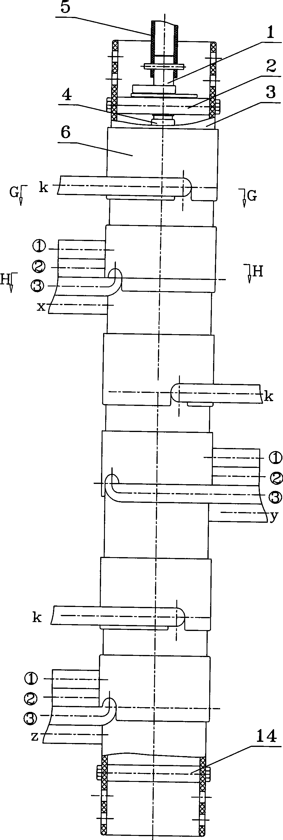
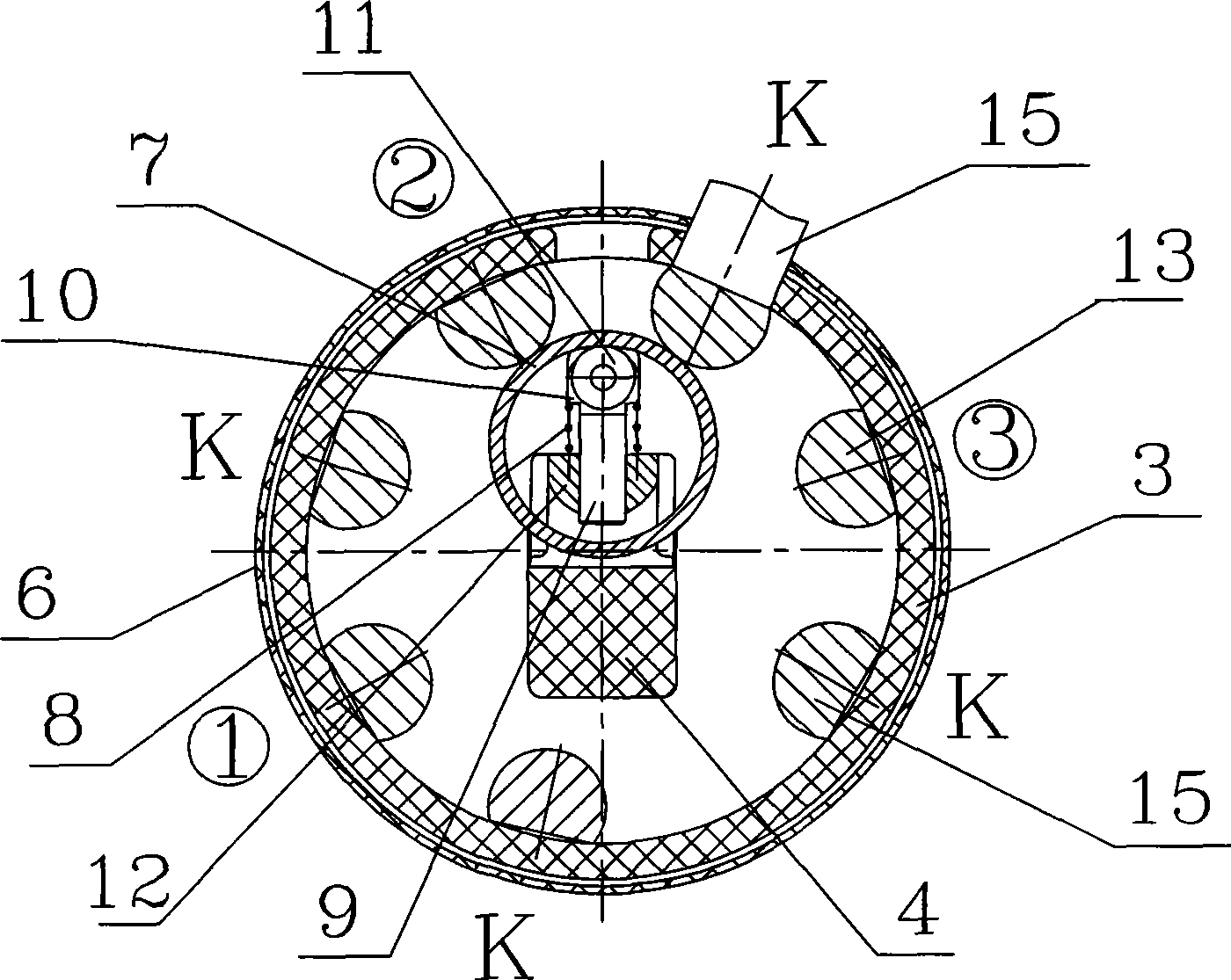
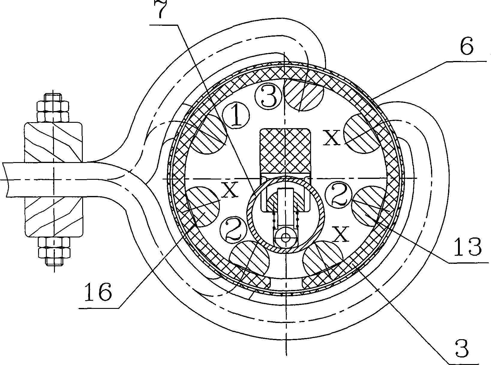
[0019] An example of the present invention is figure 1 , 2 , 3, 4, and 5, it is a vertical three-phase non-excitation neutral point five-speed forward and reverse voltage regulating tap-changer, which has a drum-shaped insulator 3 and an arc extinguishing cover 6 outside the insulator, so that the switch can be The inner electrified body is isolated from the outside world to further reduce the effective outer diameter of the switch. An upper support 2 and a lower support 14 are arranged above and below the insulator, and an insulating shaft 4 is arranged between the upper and lower supports. The upper end of the insulating shaft is connected to the The transmission shaft 1 mounted in the upper support is connected, and the upper end of the transmission shaft is connected with the switch operating structure 5. There are six layers of static contacts and moving contacts along the upper and lower sides of the switch, and each two layers corresponds to a phase. , the six layers ...


PUM


Abstract

The invention relates to forward-backward voltage regulation no-excitation tapping switch used for a transformer. The switch comprises an insulator, an upper bracket, a lower bracket and an insulating shaft. Two layers of fixed contacts and moving contacts are arranged corresponding to every phase of the switch, and the moving contacts are installed on the insulating shaft and connected with two adjacent fixed contacts at the same time. The tapping switch is characterized in that four fixed contacts linked with a tap k of a main coil and three fixed contacts linked with a tap of a voltage regulation coil are arranged on one layer in every phase; three fixed contacts for outputting x and four fixed contacts linked with the tap of the voltage regulation coil are arranged on the other layer in every phase; and the arrangement directions of the tap linkage positions of the fixed contacts which are connected with the tap of the voltage regulation coil and arranged on the opposite layers in every phase are opposite. The switch has the advantages of simple structure, convenient manufacturing, reliable working performance, low manufacturing and use costs, suitability for configuring with transformers with various structures, convenience for the simplification of a transformer structure, and good forward-backward voltage regulation effect, thereby meeting the market demands.

Description

technical field [0001] The invention relates to a non-excitation tap changer for positive and negative voltage regulation used in transformers. Background technique [0002] In the Chinese patent CN2433720Y, a non-excitation forward and reverse voltage regulating tap changer is disclosed. This tap changer has obvious advantages over the previous similar products, but there are also the following problems: the previous cage clip type tap changer switch configuration, W 1 with W 2 They are the number of turns in the voltage regulating section of the voltage regulating coil, and W is the number of turns in the main coil. The voltage regulation effect diagram is shown in Table 1: [0003] Table 1 [0004] switch position 1 2 3 4 5 Regulator position +2 +1 0 -1 -2 Upper layer moving contact position k-3 k-3 k-3 k-1 k-1 The position of the lower moving contact 1-x 2-x 3-x 2-x 3-x Coil Effective Turns W+W 1 +W 2 W+W 2 W ...

Claims


Application Information

Patent Timeline
Patent Type & Authority Applications(China)
IPC IPC(8): H01F29/04H01F41/00H01H1/56
Inventor 秦靓
Owner 秦靓
Why Eureka
Try Eureka