Voice coil assembly, loudspeaker using the same, and method for producing the same
A speaker and voice coil technology, applied in the field of voice coil components, can solve the problems of increasing the overall weight of the speaker diaphragm and reducing the production efficiency of the speaker, and achieve the effects of reducing vibration, reducing weight, and increasing the rigidity of the skeleton
- Summary
- Abstract
- Description
- Claims
- Application Information
AI Technical Summary
Problems solved by technology
Method used
Image
Examples
Embodiment approach 1
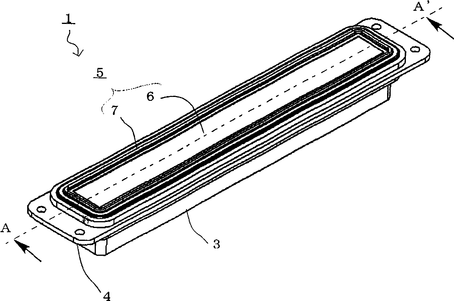
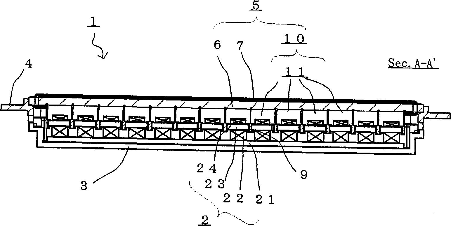
[0052] Figure 1A and 1B is a view showing a flat speaker 1 according to a preferred embodiment of the present invention. Figure 1A is a perspective view of the loudspeaker 1 showing the flat diaphragm 6 facing upwards, and Figure 1B is a cross-sectional view along the line A-A' showing the internal structure of the flat speaker 1 . These figures do not show parts of the internal structure and the like which are not necessary for the description of the present invention.
[0053] The flat and thin speaker 1 of the present embodiment is a flat and thin speaker with a speaker vibrating part 5, which includes a generally rectangular flat diaphragm 6, wherein the width W (about 16.2mm) of the flat diaphragm 6 and the overall height h of the speaker ( approximately 20.0 mm) is relatively small compared to the length L (approximately 140.8 mm) of the flat diaphragm 6 . Specifically, the speaker 1 further includes a speaker magnetic circuit 2 , a support frame 3 fixed to the bo...
Embodiment approach 2
[0068] Figure 4A and 4B is a view showing the voice coil assembly 30 of the flat speaker 1 according to another embodiment of the present invention. Figure 4A is a plan view of the voice coil assembly 30, and Figure 4B is a perspective view showing the entire voice coil assembly 30 . The voice coil assembly 30 includes a lattice bobbin 31 having a lattice cross section defining 14 rectangular spaces 31a therein, and 14 inner rectangular coils 9 each fixed to an inner wall surface 31b defining the rectangular spaces 31a. The voice coil assembly 30 of this embodiment can replace the voice coil assembly 10 of the previous embodiment to provide a flat and thin speaker 1 . Accordingly, elements similar to those of the previous embodiment, such as the magnetic circuit 2 and the loudspeaker vibrating part 5 including the flat diaphragm 6, are indicated by like reference numerals and will not be described further below.
[0069] The lattice frame 31 is obtained by injection-mol...
Embodiment approach 3
[0075] Figure 5A and 5B is a view showing the magnetic circuit 20 used in the speaker 1 according to another preferred embodiment of the present invention. Figure 5A is a perspective view of the magnetic circuit module 2m showing the magnetic circuit 20, and Figure 5B is a perspective view showing the magnetic circuit 20 . Figure 5A and 5B The magnetic circuit 2 shown in includes six magnetic circuit modules 2m connected together. Particularly, Figure 5A and 5BThe magnetic circuit 20 includes three magnetic circuit modules 2a and three magnetic circuit modules 2b alternately along a single row (the magnetization direction of which is opposite to that of the magnetic circuit modules 2a) such that adjacent magnets have different polarities.
[0076] Each magnetic circuit module 2m includes a generally rectangular flat plate 23, a main magnet 22 fixed to the bottom surface of the plate 23, a yoke fixed to the bottom surface of the main magnet 22, and a repulsion magnet...
PUM
| Property | Measurement | Unit |
|---|---|---|
| Size | aaaaa | aaaaa |
| Thickness | aaaaa | aaaaa |
Abstract
Description
Claims
Application Information
 - R&D
- Intellectual Property
- Life Sciences
- Materials
- Tech Scout
- Unparalleled Data Quality
- Higher Quality Content
- 60% Fewer Hallucinations
Browse by: Latest US Patents, China's latest patents, Technical Efficacy Thesaurus, Application Domain, Technology Topic, Popular Technical Reports.
© 2025 PatSnap. All rights reserved.Legal|Privacy policy|Modern Slavery Act Transparency Statement|Sitemap|About US| Contact US: help@patsnap.com


