
High density perforating gun system producing reduced debris

A technology of high-energy explosives and equipment, which is applied in launching devices, boreholes/well components, explosive charges, etc., and can solve problems such as low perforation efficiency, debris formation, and perforation blockage

Inactive Publication Date: 2009-06-24
OWEN OIL TOOLS
View PDF2 Cites 3 Cited by
  • Summary
  • Abstract
  • Description
  • Claims
  • Application Information

AI Technical Summary

Problems solved by technology

This debris is undesirable because it must be removed with a wireline or other device during a secondary operation, and because it may block the perforations created by the perforating operation, making perforating inefficient and sometimes Requires repeated perforation operations
Thus the invention of Chawla et al. has problems with both "dead zones" and debris formation

Method used


Image

  • High density perforating gun system producing reduced debris
  • High density perforating gun system producing reduced debris
  • High density perforating gun system producing reduced debris

Examples


Embodiment Construction

[0022] The present invention relates to an apparatus and method for perforating a wellbore. The invention is susceptible to embodiments in different forms. While the drawings illustrate and herein describe in detail specific embodiments of the invention, it should be understood that the disclosure is to be considered as an illustration of the principles of the invention and is not intended to limit the invention to what is illustrated and described herein. invention.

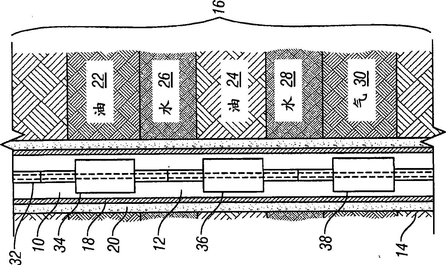
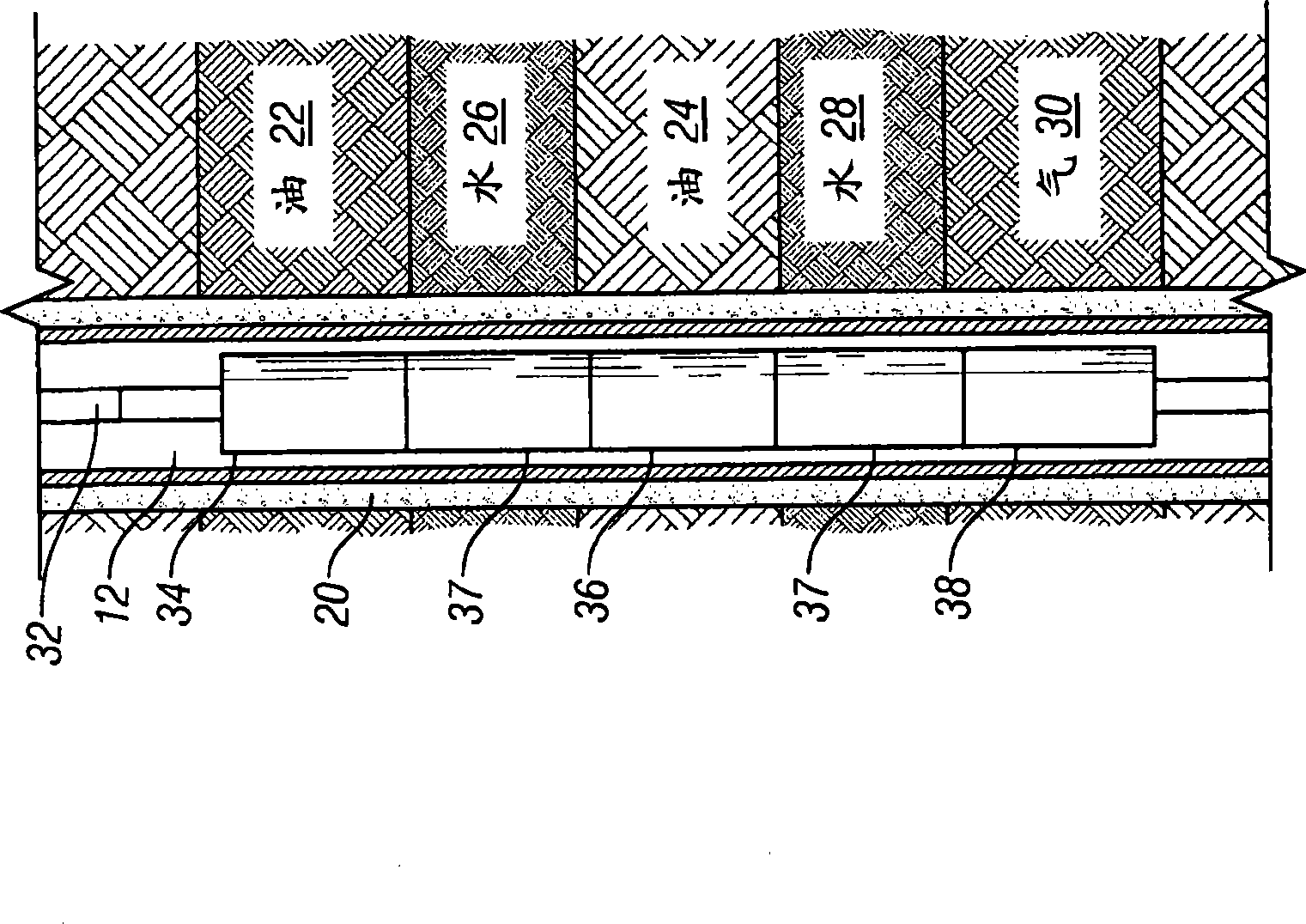
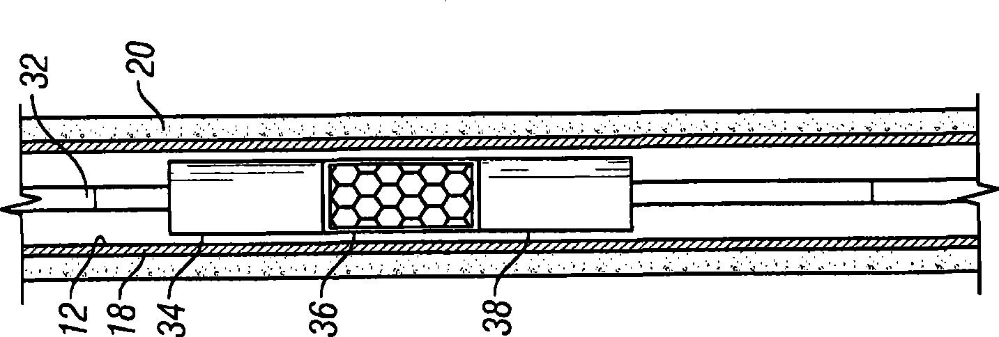
[0023] figure 1 An exemplary perforating system 10 constructed in accordance with one embodiment of the present invention is illustrated. Perforation system 10 is disposed within wellbore 12 that has been drilled through formation 14 and hydrocarbon-bearing formation 16 . Portions of the wellbore 12 are cased with steel casing 18 secured by cement 20 within the open wellbore bore.

[0024] The hydrocarbon-bearing formation 16 includes two oil-bearing formations 22 , 24 separated by a water layer 26 . Water ...


PUM


Abstract

A perforating system has a perforating module comprising a unitary body of explosive. The explosive is contained within a non-explosive casing, or liner, having formed indentations and a cover thereover. The indentations, which will transform into explosively formed penetrators (EFP's) upon detonation, have a perimeter shape that allows for improved packing density, e.g., a hexagonal perimeter, which results in relatively little ''dead space'' wherein no perforating penetrators are generated. In operation, the module provides a relatively dense shot pattern and substantially reduced amount of post-detonation debris that could clog the perforations and / or require remedial clean-up or repeat perforation.

Description

technical field [0001] The present invention generally relates to the design of perforating tools for forming perforations in a wellbore to improve the flow of fluids from the wellbore. Background technique [0002] Perforating guns are used within the wellbore bore to increase the permeability of the formation surrounding the wellbore. In general, a perforating gun that produces a greater number of perforations is considered more effective than one that produces fewer perforations. Therefore, it is often desirable to maximize the number of perforating jets within a section of a wellbore. However, this can be difficult because there are constraints regarding the arrangement of charges used for perforating. A standard shaped charge has an outer casing made of metal or other material that encloses a high explosive charge. Shaped charge holders have an opening generally with a circular perimeter. When the charges are filled in the charge tube in a contiguous manner, spaces ...

Claims


Application Information

Patent Timeline
Patent Type & Authority Applications(China)
IPC IPC(8): F41F5/00
CPCF42B1/028E21B43/117F42D3/04
Inventor D·W·普拉特M·S·乔拉
Owner OWEN OIL TOOLS
Learn More