All-purpose leakage protection plug for ground wire live trip
A leakage protection plug, live ground wire technology, applied in the direction of automatic disconnection of emergency protection devices, emergency protection circuit devices, circuits, etc., can solve problems such as safety hazards, and achieve the effect of improving safety and solving safety hazards
- Summary
- Abstract
- Description
- Claims
- Application Information
AI Technical Summary
Problems solved by technology
Method used
Image
Examples
Embodiment 1
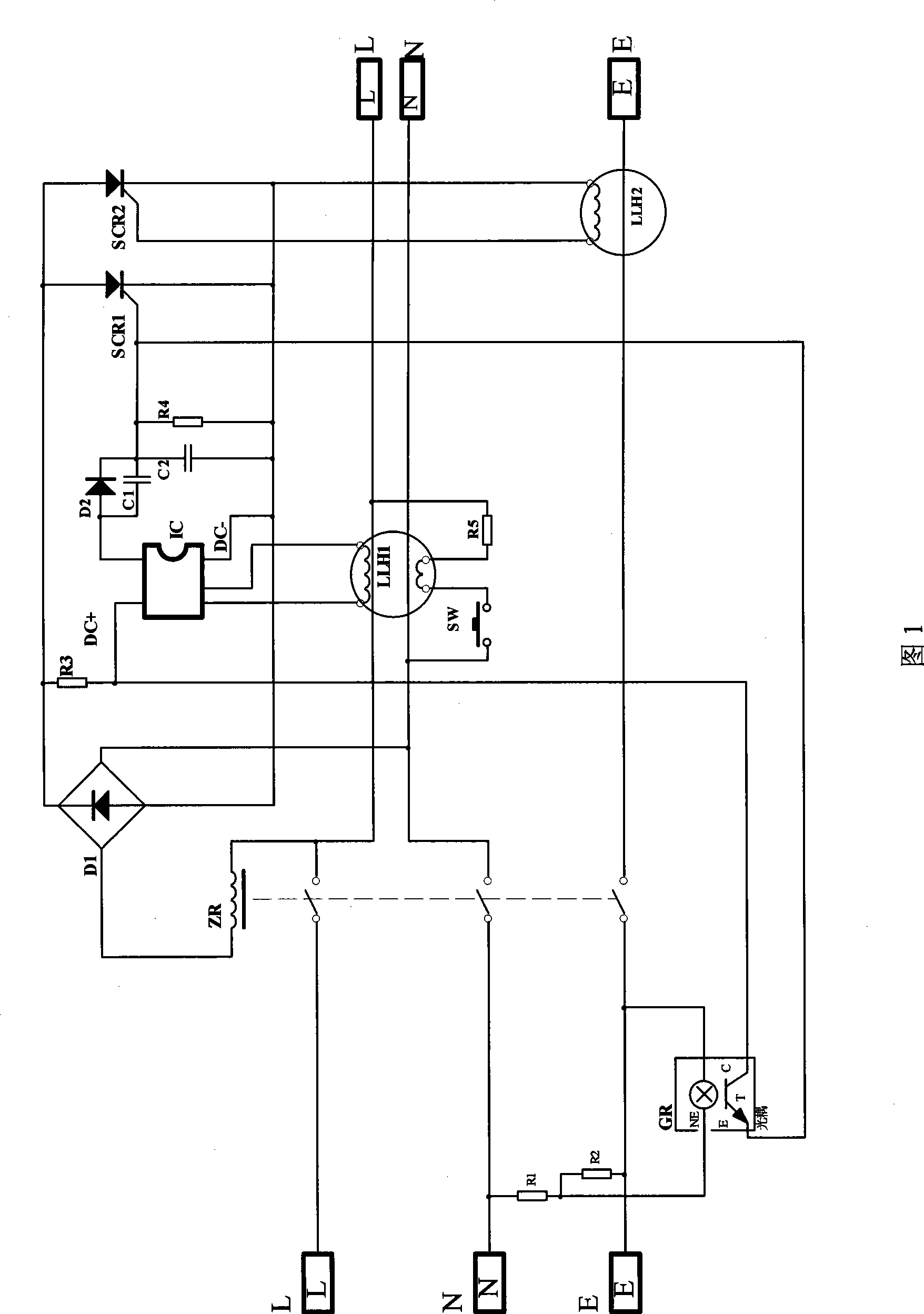
[0019] As shown in Figure 1, the leakage protection plug for ground wire live tripping includes zero-sequence current transformer LLH1, thyristor SCR1, tripping coil ZR, amplifier circuit IC, rectifier D1, test circuit SW and resistor R5; optocoupler GR The neon lamp NE inside is connected in parallel with resistor R2, and then connected in series with resistor R1, and the two ends connected in series are connected with the zero line N pole and the ground line pole of the input end of the leakage protection plug; the collector of the phototransistor T in the optocoupler GR C is connected to the positive pole DC+ of the amplifying circuit IC in the leakage protector, the emitter E of the phototransistor in the optocoupler GR is connected to the trigger pole of the thyristor SCR1 in the leakage protector, and the trigger pole of the thyristor SCR1 is connected to The power supply negative pole DC- of the amplifying circuit IC in the leakage protector is connected between the resi...
Embodiment 2
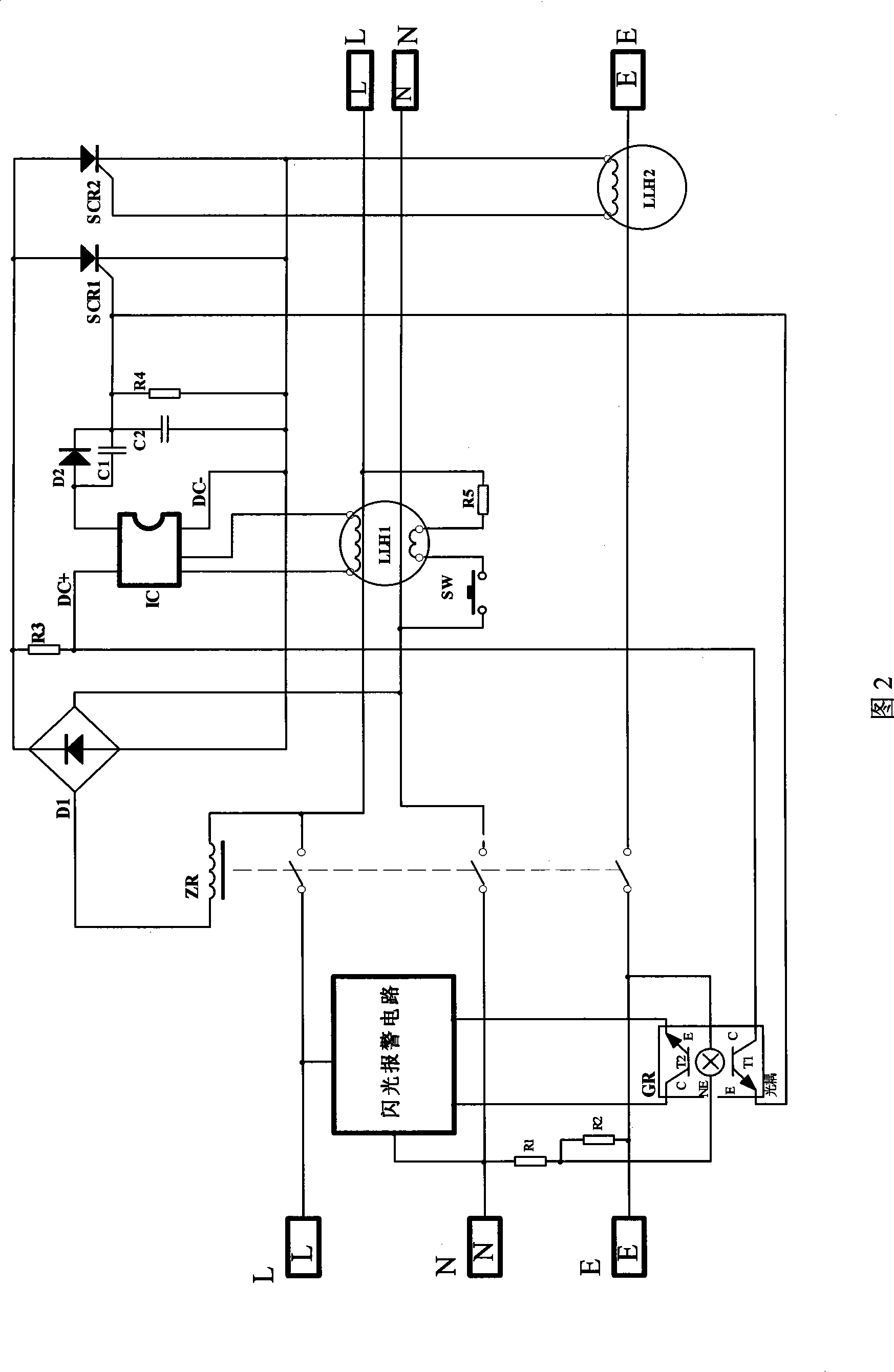
[0025] As shown in Figure 2, on the basis of Figure 1, two phototransistors T1 and T2 are installed in the optocoupler GR, and the phototransistors T1 and T2 are installed on both sides of the symmetry of the neon lamp NE. The connection is the same as that in Figure 1, and the phototransistor T2 is connected to the control terminal of the flash circuit to control the flash circuit.
[0026] The applicant for the above-mentioned flashing circuit has already applied for a patent, and it may also be a commonly used flashing alarm circuit.
[0027] Figure 1 only trips and cuts off the power when the ground wire is charged or the neutral line N and the phase line L are misaligned. Figure 2 adds an alarm circuit on the basis of Figure 1. The purpose is to: The misalignment of the line L can not only trip the power, but also flash the alarm, which can further remind the user to eliminate the corresponding fault.
Embodiment 3
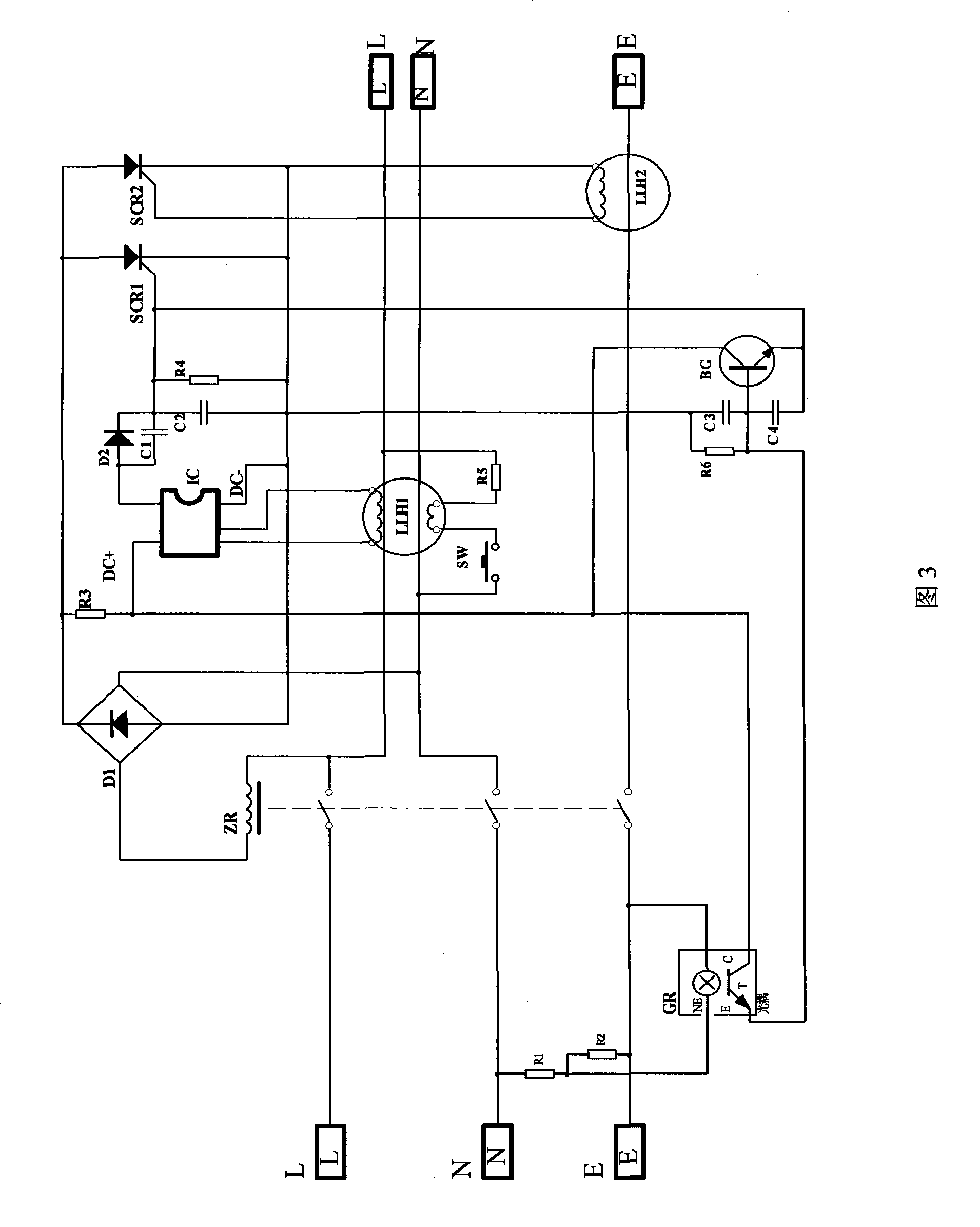
[0029] As shown in Figure 3, on the basis of Figure 1, the triode BG, resistor R6, capacitors C3, C4 are added, the emitter E of the photosensitive transistor T in the optocoupler GR is connected to the base of the triode BG, and the resistor R6 is connected in parallel with the capacitor C3 , one end of the parallel connection is connected to the base of the triode T, the other end is connected to the negative pole of the power supply DC- of the amplifying circuit IC in the leakage protector, the capacitor C4 is connected between the base and the emitter of the triode BG, and the emitter of the triode BG is connected to The trigger electrode of the thyristor SCR1 in the leakage protector is connected, the collector of the triode BG is connected to the positive pole of the power supply DC+ of the amplifier circuit IC in the leakage protector, and the connection method of other components is the same as that in Figure 1.
[0030] The above circuit is set up to increase the trigg...
PUM
 Abstract
Description
Claims
Application Information
 - R&D
- Intellectual Property
- Life Sciences
- Materials
- Tech Scout
- Unparalleled Data Quality
- Higher Quality Content
- 60% Fewer Hallucinations
Browse by: Latest US Patents, China's latest patents, Technical Efficacy Thesaurus, Application Domain, Technology Topic, Popular Technical Reports.
© 2025 PatSnap. All rights reserved.Legal|Privacy policy|Modern Slavery Act Transparency Statement|Sitemap|About US| Contact US: help@patsnap.com


