
Coil connecting line construction for transformer

A technology for transformers and high-voltage coils, applied in the field of transformers, can solve problems such as tight insulation distances and complex wiring structures, and achieve the effects of increasing insulation distances, simplifying wiring structures, and solving wiring difficulties

Inactive Publication Date: 2009-06-17
TEBIAN ELECTRIC APP CO LTD
View PDF0 Cites 5 Cited by
  • Summary
  • Abstract
  • Description
  • Claims
  • Application Information

AI Technical Summary

Problems solved by technology

However, for an autotransformer with a voltage level of 500kV at the end of the high-voltage coil (the head end of the medium-voltage coil), when this conventional structure is adopted, when the 500kV lead wire passes through the other column from one column, the clamp web, clip The insulation distance of parts such as the oil guide box, the magnetic shield of the clip, and the drawstring frame are very tight, and the wiring structure is relatively complicated. Therefore, the 500kV connection method at the end has also become a difficult point in the design of the ultra-high voltage autotransformer

Method used


Image

  • Coil connecting line construction for transformer
  • Coil connecting line construction for transformer
  • Coil connecting line construction for transformer

Examples


Embodiment 1

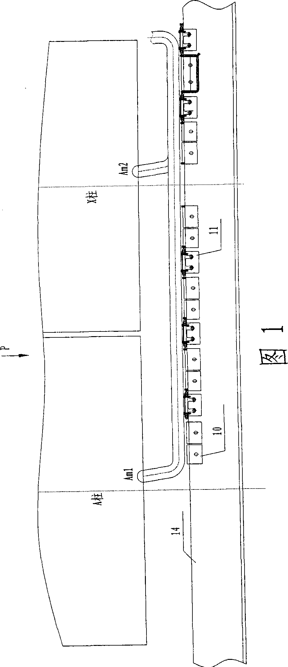
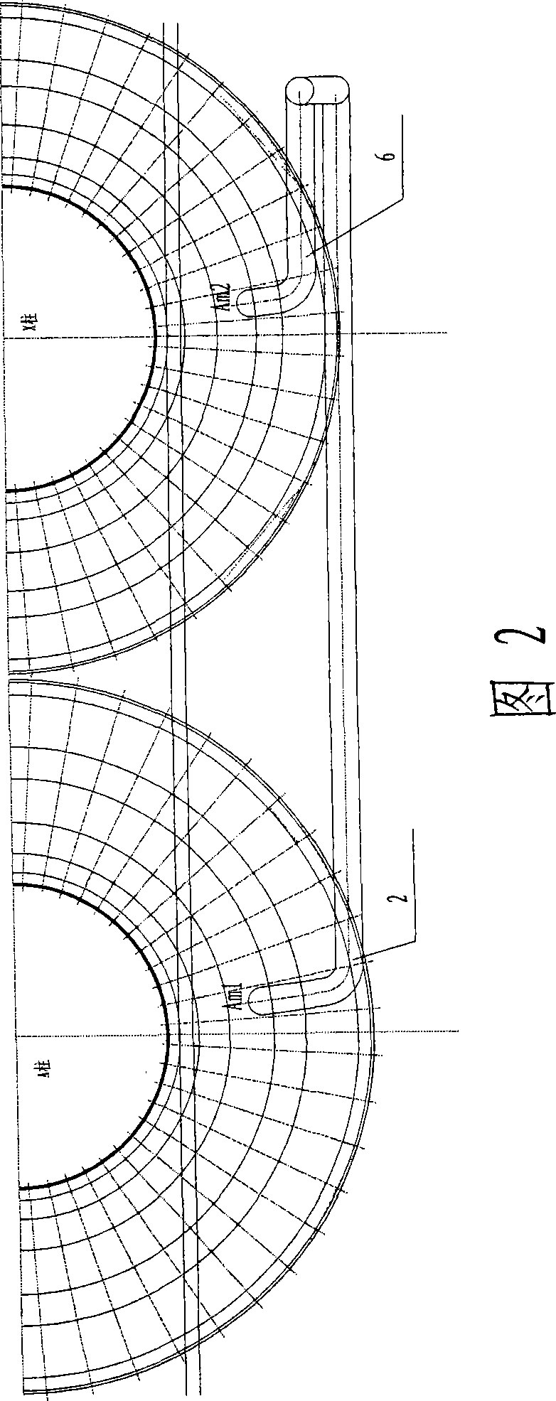
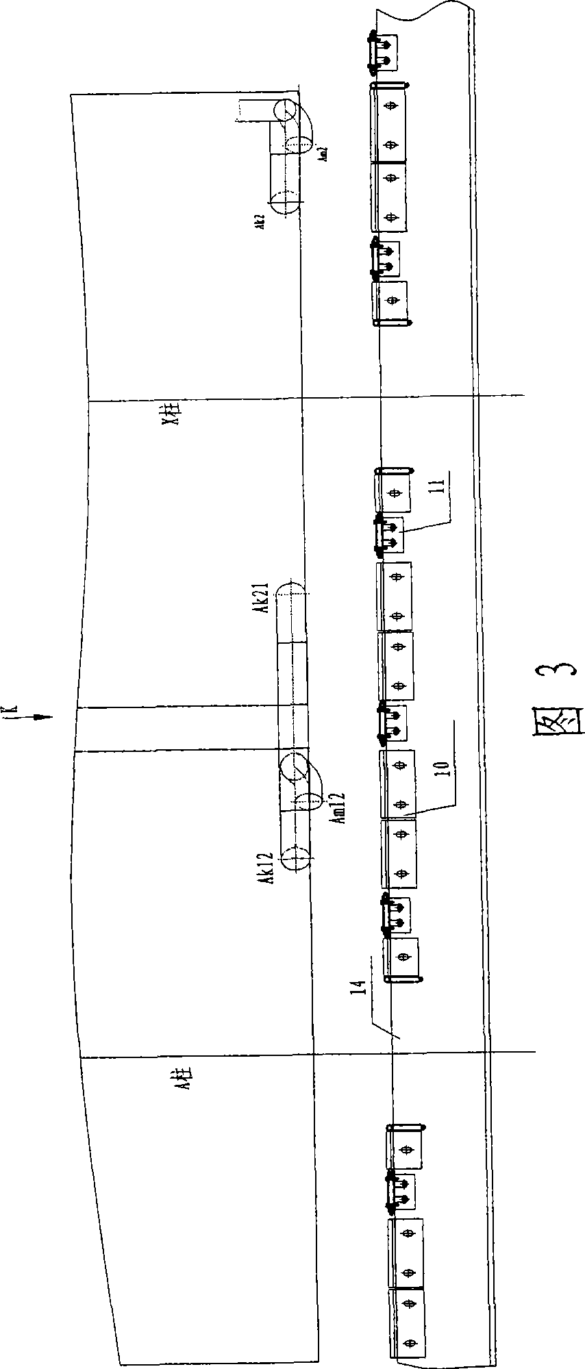
[0018] As shown in Figures 3 and 4, the coil connection structure of the transformer of the present invention includes an A-pillar coil and an X-pillar coil. Both the A-pillar coil and the X-pillar coil include a high-voltage coil and a medium-voltage coil. According to the structural characteristics of the equal potential between the end of the high voltage coil and the head end of the medium voltage coil, the high voltage coil end outlet 1 of the A-pillar and the medium voltage coil head end 2 of the A-pillar are connected to form a first connection line 3. The high-voltage coil electrostatic plate 12 of the X-pillar is provided with a notch along the circumferential direction, and a connecting wire 4 is placed at the notch. The connecting wire 4 passes through the electrostatic plate 12 in the radial direction of the electrostatic plate, and connects the wire outlet 5 and the first Connection 3 is connected, the other end of which is connected with the end of the high voltage c...


PUM


Abstract

The invention discloses a coil connecting wire structure in a transformer, which comprises an A cylindrical coil and an X cylindrical coil. Both of the A cylindrical coil and the X cylindrical coil comprise a high tension coil and a medium tension coil, wherein an end extended section of the high tension coil of an A cylinder is connected with an head extended section of the medium tension coil of the A cylinder to form a first connecting wire, a notch is arranged peripherally on a static board of the high tension coil of an X cylinder, a connecting conductor is positioned at the notch, the connecting conductor penetrates through the static board along the radial direction of the static board, one end of the connecting conductor is connected with the first connecting wire and the other end is connected with the end extended section of the high tension coil of the X cylinder to form a medium connecting wire, then the medium connecting wire is connected with the head extended tension of the medium tension coil of the X cylinder to form a second connecting wire, and the second connecting wire is led to a wire outlet end. The invention can structurally meet the distance requirements of electrical insulation and also can simplify structure and facilitate construction.

Description

Technical field [0001] The invention belongs to the technical field of transformers, and relates to a coil connection structure of a transformer, in particular to a coil connection structure of a high-voltage oil-immersed power transformer with a voltage level of 500 kV. Background technique [0002] For single-phase ultra-high voltage, ultra-large-capacity oil-immersed autotransformers, there are many coil turns. In order to meet the outer limit of transportation, double-column or multi-column coils are often used in parallel. For the dual-column single-phase autotransformer, the current conventional structure is to axially lead out the first end of the medium voltage coil of one column and pass through the pressure plate, lead to the outside of the coil and pass through the pressure plate of the other column, and The medium pressure head ends of the column are drawn side by side, and then lead to the outside to connect the medium pressure head ends of the two columns and connec...

Claims


Application Information

Patent Timeline
Patent Type & Authority Applications(China)
IPC IPC(8): H01F41/10H01F27/28
Inventor 方明徐思华
Owner TEBIAN ELECTRIC APP CO LTD
Learn More