Discharge lamp circuit protection and regulation apparatus
A circuit protection and adjustment device technology, applied in lighting devices, electric light sources, electrical components, etc., can solve the problems of unstable CCFL inverters and inability to adapt automatically, avoid unstable work and sudden changes in current, and achieve automatic adaptation. And the effect of adjusting and simplifying the circuit structure
- Summary
- Abstract
- Description
- Claims
- Application Information
AI Technical Summary
Problems solved by technology
Method used
Image


Examples
no. 1 Embodiment
[0049] figure 2 Shown is a lamp voltage LV signal detection circuit according to a first embodiment of the present invention. Taking the application of 4 lamps in phase as an example, the principle of the first specific embodiment will be described in detail. Step S1: Extracting electrical signals in one or more discharge lamp circuits, wherein the electrical signals are voltage sampling signals, LV1, LV2, LV3 and LV4 are sampled lamp voltages, and the four lamp voltages are in phase. Connect the detection branch at the point where the lamp voltage is sampled.
[0050] Step S2: Synthesize the electrical signals into a voltage detection signal representing the working state of the discharge lamp through a logic circuit, and each detection branch includes a voltage detection signal connected to the DC bias voltage V bias and the bias resistor R between the lamp voltage sampling point s , the lamp voltage sampling signals LV1 / LV2 / LV3 / LV4 are respectively connected to the lamp...
no. 2 Embodiment
[0064] The second specific embodiment is an extension of the first specific embodiment, and the step S2 is divided into steps S21 and S22. Steps S21 and S22 will be described in detail below.
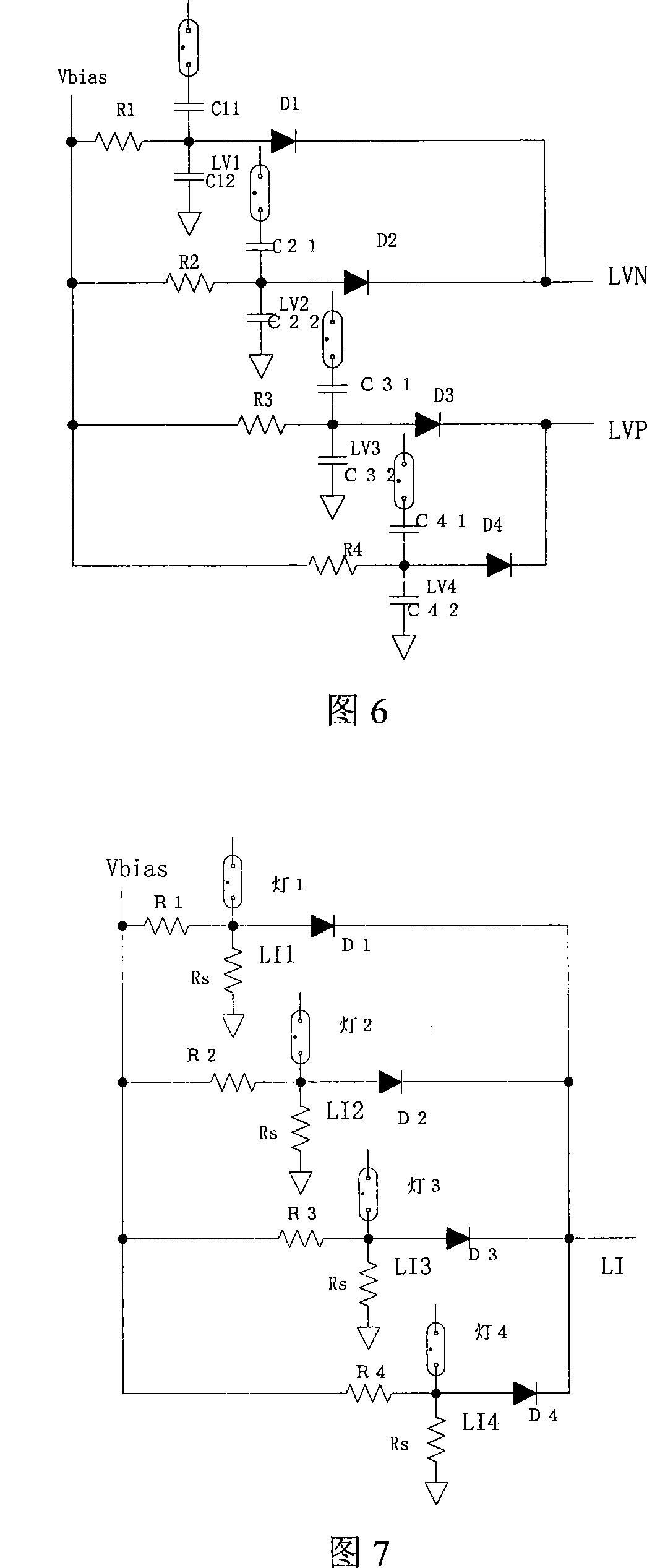
[0065] Step S21: Divide the discharge lamps into at least one group of discharge lamp groups with the same voltage or current phase; divide the discharge lamps into two groups, wherein the voltage phases of the first group and the second group of discharge lamps are opposite, and one is coupled to A first detection circuit of the discharge lamps of the first group obtains a first electrical signal and a second electrical signal is obtained from a second detection circuit coupled to the discharge lamps of the second group, when said first or second electrical signal is short-circuited state, the short-circuit protection is activated. The electrical signal may be a current signal or a voltage signal. Figure 6 It is the out-of-phase application of 4 lamps according to the second embodim...
no. 3 Embodiment
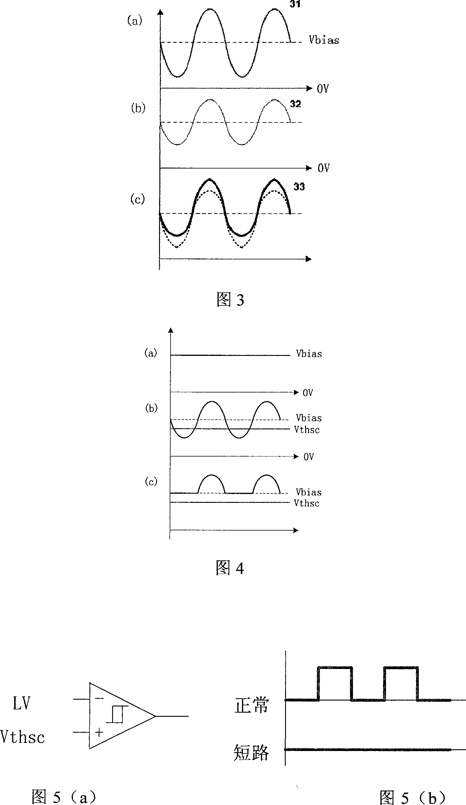
[0072] Figure 7 It is a schematic diagram of a LI signal detection OR gate circuit for 4 lamps in phase according to the third embodiment of the present invention. Its working principle is the same as that of the first embodiment, but the lamp current is used instead of the lamp voltage. The point of sampling the lamp current is connected to one end of the lamp tube, and through the sampling resistor R s grounded. Connect the detection branch at the point where the lamp current is sampled. Each detection branch is connected with a diode, and the four diodes in the figure form an OR gate. Comparing the LI signal instead of the LV signal in Figure 5 with a threshold value can realize the open circuit protection of the lamp, and its principle is consistent with that of using the LV signal to realize protection.
PUM
 Abstract
Description
Claims
Application Information
 - R&D
- Intellectual Property
- Life Sciences
- Materials
- Tech Scout
- Unparalleled Data Quality
- Higher Quality Content
- 60% Fewer Hallucinations
Browse by: Latest US Patents, China's latest patents, Technical Efficacy Thesaurus, Application Domain, Technology Topic, Popular Technical Reports.
© 2025 PatSnap. All rights reserved.Legal|Privacy policy|Modern Slavery Act Transparency Statement|Sitemap|About US| Contact US: help@patsnap.com