Partial coil in magnetic resonance equipment, the magnetic resonance equipment and imaging method

A technology of magnetic resonance equipment and local coils, applied in magnetic resonance measurement, material analysis through resonance, magnetic property measurement, etc., can solve problems such as low shimming efficiency, uneven distribution of the main magnetic field, and reduced image quality, and achieve Improve the uniformity of the main magnetic field and improve the effect of local imaging quality

Active Publication Date: 2011-10-19
SIEMENS HEALTHINEERS LTD
View PDF4 Cites 0 Cited by
  • Summary
  • Abstract
  • Description
  • Claims
  • Application Information

AI Technical Summary

Problems solved by technology

[0005] 1. Each area in the cavity can only achieve passive shimming, that is, the shimming effect of each area is completely determined by the shimming coil in the body coil 11, so that local imaging can be realized in some areas with poor shimming effect The image quality is not high, such as areas that are not concentric (also called eccentric) with the main magnetic field; and, because the shim coils are located inside the gradient coils, their position is limited by the position of the gradient coils, so they are far away from some local areas, Therefore, the electromagnetic fields generated in these local areas are also weak, making the shimming efficiency not high
[0006] 2. The shim coils are generally integrated inside the gradient coils. The distance between the gradient coils and the shim coils is usually less than or equal to 1 cm, and the directions of the magnetic fields generated by the two are parallel to each other (all parallel to the main magnetic field direction B0), so that As a result, electromagnetic field coupling between the two is prone to occur, which interferes with each other's performance, thereby reducing image quality
[0007] 3. Due to the uneven distribution of the main magnetic field in each area of ​​the cavity, various technical means that require high shimming effects cannot be applied to existing magnetic resonance equipment, for example, using echo planar imaging (EPI) pulse sequences Driving gradient coils, or imaging techniques for water-fat separation, etc., so that high-quality images cannot be obtained

Method used


Image

  • Partial coil in magnetic resonance equipment, the magnetic resonance equipment and imaging method
  • Partial coil in magnetic resonance equipment, the magnetic resonance equipment and imaging method
  • Partial coil in magnetic resonance equipment, the magnetic resonance equipment and imaging method

Examples


Embodiment Construction

[0027] In order to make the object, technical solution and advantages of the present invention clearer, the present invention will be further described in detail below with reference to the accompanying drawings and examples.

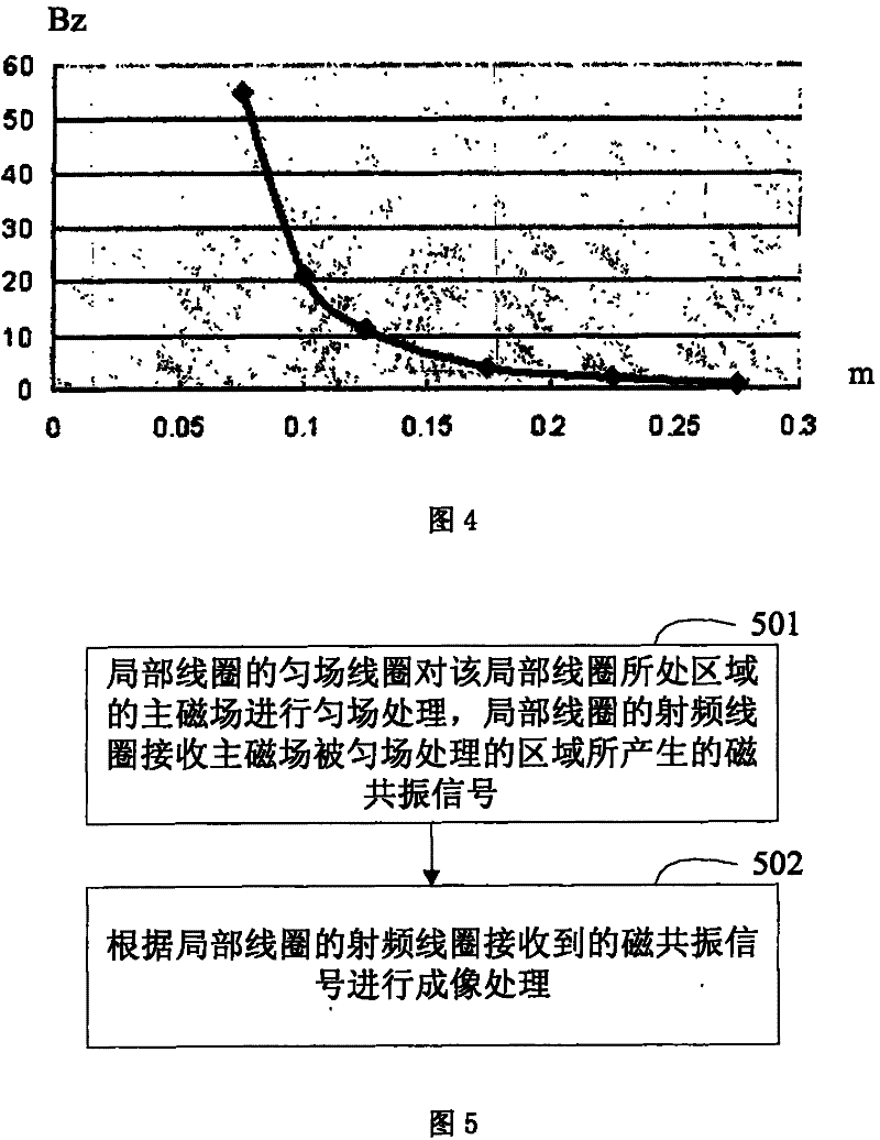
[0028] Fig. 2 is a schematic structural diagram of a magnetic resonance device in an embodiment of the present invention. Referring to Fig. 2, the magnetic resonance equipment in the embodiment of the present invention comprises: figure 1 11 in the same body coil. compared to figure 1 , in the cavity formed by the body coil 11 , the magnetic resonance apparatus shown in FIG. 2 in the embodiment of the present invention further includes: a local coil 22 .

[0029] Fig. 3 is a schematic structural diagram of a local coil in an embodiment of the present invention. Referring to FIG. 3 , the local coil 22 includes a radio frequency coil 31 and a shim coil 32 . In FIG. 3 , the radio frequency coil 31 is disposed inside the shim coil 32 . The radio freque...


PUM


Abstract

The present invention discloses a partial coil in a magnetic resonance device. The partial coil according to the invention is composed of a first coil and a second coil, wherein the second coil executes a field homogenizing procession to the area in which the partial coil is. The main field homogeneity of the area is increased. Furthermore the magnetic field generated by the first coil which receives the magnetic resonance signal and magnetic field generated by the second coil that executes the field homogenizing procession are not parallel, thereby the first coil and the second coil do not couple with each other for preventing the capability effect between the first coil and the second coil, and the partial imaging quality of area in which the partial coil is can be increased. Furthermore, the partial coil is installed on certain areas with inferior field homogenizing effect, such as area which is non-homocentric to the main magnetic field, and the effect for increasing the partial imaging quality is especially evident.

Description

technical field [0001] The present invention relates to magnetic resonance technology, in particular to a local coil in magnetic resonance equipment, a magnetic resonance equipment, and a local imaging method in the magnetic resonance equipment. Background technique [0002] figure 1 It is a structural schematic diagram of the existing magnetic resonance equipment. see figure 1 , the magnetic resonance equipment includes a body coil 11 , and the patient is located in a cavity formed by the body coil 11 . [0003] Wherein, the body coil 11 sequentially includes: a radio frequency coil, a gradient coil and a shim coil from inside to outside. The radio frequency coil and the gradient coil generate a radio frequency magnetic field and a gradient magnetic field respectively, and magnetic resonance signals can be generated in the region where the two magnetic fields have the same frequency. Afterwards, the radio frequency coil receives and outputs the generated magnetic resona...

Claims


Application Information

Patent Timeline
Patent Type & Authority Patents(China)
IPC IPC(8): G01R33/20G01R33/36G01R33/38G01R33/385A61B5/055
Inventor 刘克成陶红艳高静
Owner SIEMENS HEALTHINEERS LTD
Why Eureka
Try Eureka