
Bias cutter

An oblique cutting machine and pivot technology, which is used in metal sawing equipment, sawing machine devices, metal processing equipment, etc., can solve the problems affecting the packaging volume of the oblique cutting machine, the packaging volume becomes larger, and the life of the torsion spring is shortened. The effect of packaging volume, smooth transmission, and shortened vertical distance

Inactive Publication Date: 2009-06-10
POSITEC POWER TOOLS (SUZHOU) CO LTD
View PDF0 Cites 8 Cited by
  • Summary
  • Abstract
  • Description
  • Claims
  • Application Information

AI Technical Summary

Problems solved by technology

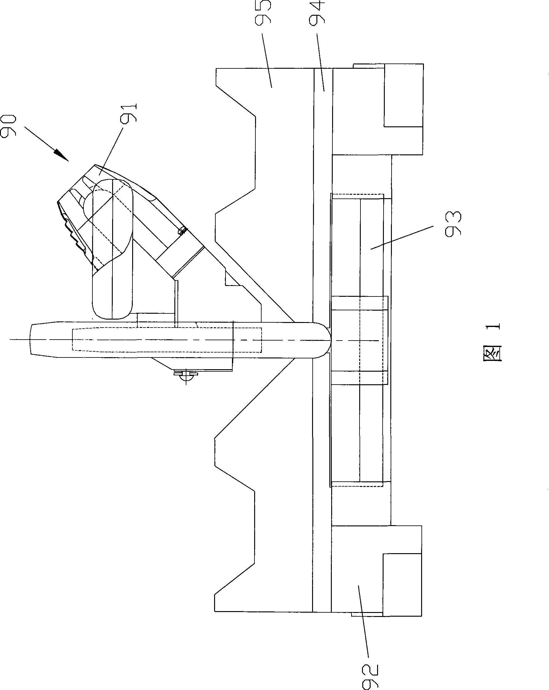
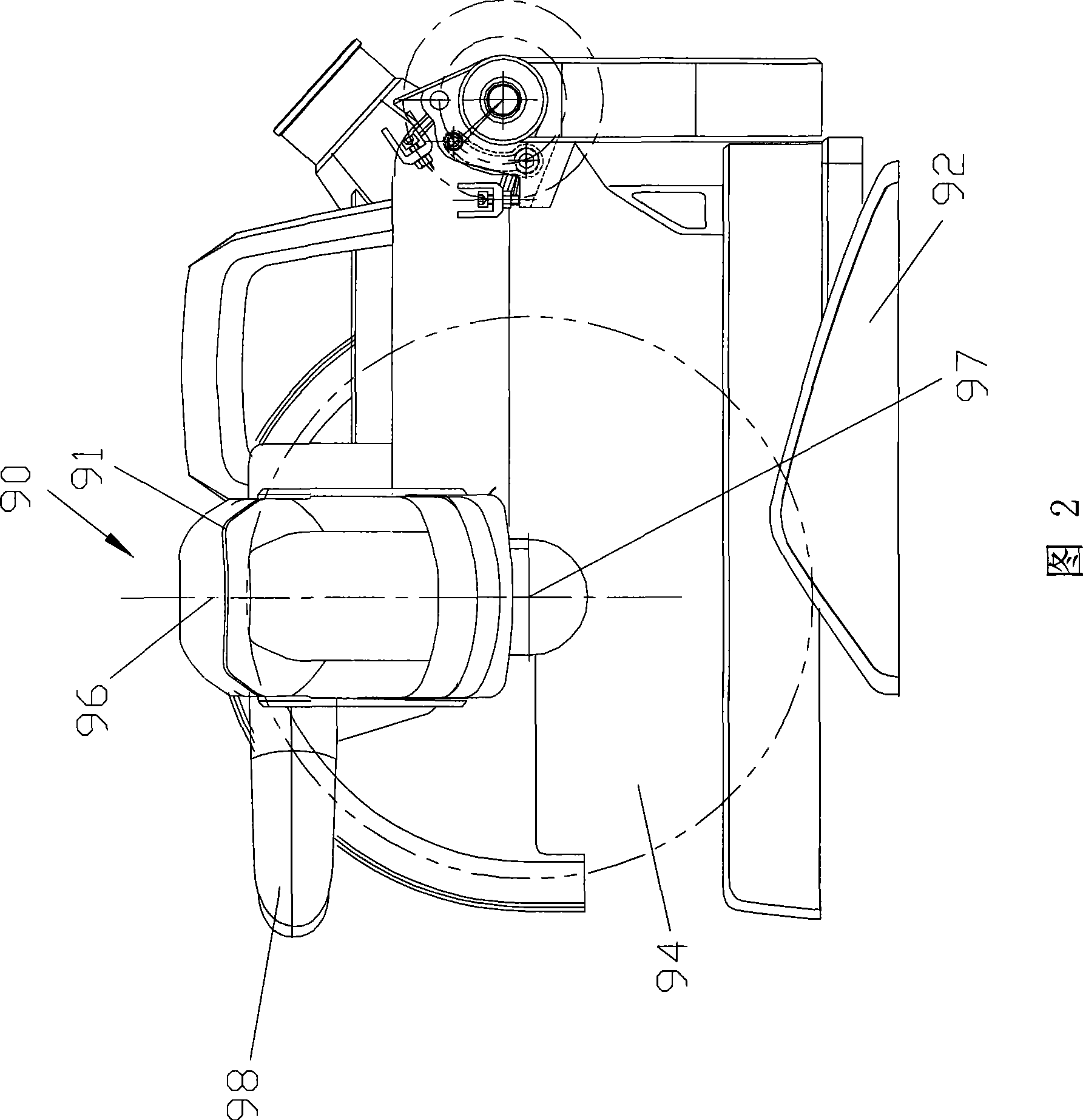
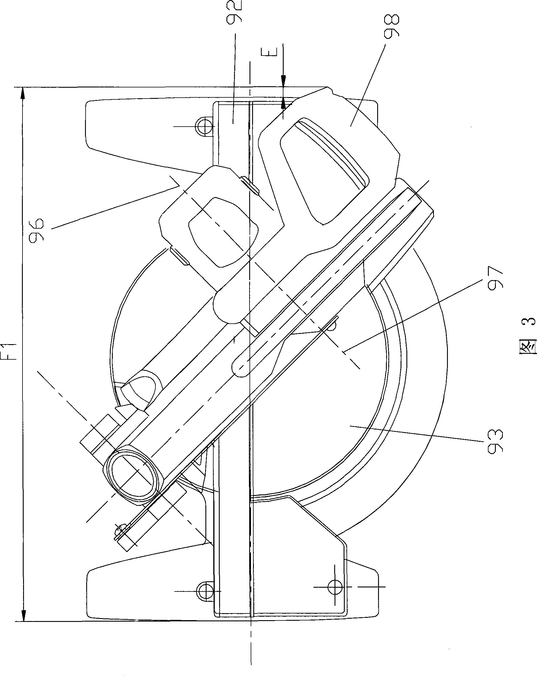
The handle 98 is fixedly arranged on the motor 91, and in order to make the operator operate comfortably, the handle 98 needs a certain size, and in the packaging of the whole bevel cutting machine, because the motor 91 is relatively arranged in front, the handle 98 will often affect the entire machine. Packing Volume of Miter Cutting Machine
As shown in Figure 3, the handle 98 protrudes outside the base 92 during packaging, and the distance outside the base 92 protruding from the handle 98 is E, so that the distance E will be increased in the width direction during packaging, and the packaging width is F1 , the packaging volume of the whole machine becomes larger, thereby increasing the cost; and because the weight of the motor 91 in the saw mechanism 90 is the largest, the center of gravity of the entire saw mechanism 90 is close to the motor 91, and because the motor 91 is relatively arranged in front, the saw mechanism 90 The vertical distance between the center of gravity of the saw mechanism and the pivot axis of the saw mechanism is relatively long, so the moment arm increases, which shortens the life of the torsion spring installed on the pivot axis
Moreover, the bevel gear is used as the transmission mechanism. Since the bevel gear transmission is equivalent to a pair of pure rolling without sliding of friction cones, the transmission is not stable and the noise is relatively large.

Method used


Image

  • Bias cutter
  • Bias cutter
  • Bias cutter

Examples


Embodiment Construction

[0034] Below just with preferred embodiment, will illustrate the creative conception of the present utility model.

[0035] As shown in Figure 4, in the first preferred embodiment of the present invention, the bevel cutting machine includes a base 1, a workbench 8 that is rotatably connected to the base 1, a support arm 2 that is movably connected to the workbench 8, and a movable The saw mechanism 3 connected to the support arm 2, wherein the support arm 2 is pivotally arranged on the workbench 8 through the first pivot 21, and the saw mechanism 3 is pivotally arranged on the support arm 2 through the second pivot 31 Come up to realize the cutting workpiece. The base 1 has front and rear sides, wherein the front side is close to the operator, and the rear side is opposite to the front side. The second pivot 31 is used as the pivot shaft of the saw mechanism 3, on which a torsion spring (not shown) is also sleeved, so that the operator presses the saw mechanism 3 to pivot, co...


PUM


Abstract

The invention provides an oblique cutting machine, which comprises a base, a support arm in match connection with the base, as well as a sawing mechanism in movable match connection with the support arm. The sawing mechanism comprises a round saw blade, a motor and a transmission mechanism; the motor is obliquely arranged on one side of the round saw blade and is in match connection with a motor output shaft; and the round saw blade is in match connection with a saw-blade shaft, wherein the motor output shaft is obliquely arranged backwards relative to the saw-blade shaft. Therefore, the motor is also arranged relatively behind the oblique cutting machine, so as to reduce packaging volume and cost, shift the gravity center of the sawing mechanism, shorten force arm and increase the life span of a torsional spring of the sawing mechanism. In addition, as a hypoid gear is utilized as the transmission mechanism, the oblique cutting machine can reduce noise during cutting operation and is smooth in transmission, so as to improve cutting precision.

Description

technical field [0001] The invention relates to a bevel cutting machine, in particular to a bevel cutting machine capable of realizing double pendulums. Background technique [0002] A traditional miter cutting machine includes a base for placing workpieces, a support arm connected to the base, and a saw mechanism connected to the support arm, wherein the support arm drives the saw mechanism to perform oblique cutting relative to the vertical position, and due to The motor in the traditional oblique cutting machine is set horizontally, so that the support arm can only tilt to one side relative to the vertical position, otherwise the motor shell will interfere with the workbench or base, so the traditional oblique cutting machine generally can only move to one side Tilt to the left to cut the workpiece, and its maximum tilt angle is about 45 degrees. And this kind of oblique cutting machine can only realize one-way oblique cutting to the left, so when it is necessary to obli...

Claims


Application Information

Patent Timeline
Patent Type & Authority Applications(China)
IPC IPC(8): B23D47/00B23D45/04B23D47/12
Inventor 沃伦·布朗哈利·索默格雷厄姆·格哈德
Owner POSITEC POWER TOOLS (SUZHOU) CO LTD
Learn More