
Shield mounting structure of helmet

A technology for installing structures and shields, which is applied to helmets, helmet covers, clothing, etc., can solve the problems of high production cost, troublesome installation, and unnaturalness, and achieve the effect of easy cost reduction, low cost, and simple assembly and disassembly

Active Publication Date: 2009-06-03
OGK KABUTO
View PDF1 Cites 11 Cited by
  • Summary
  • Abstract
  • Description
  • Claims
  • Application Information

AI Technical Summary

Problems solved by technology

[0008] At this time, the direction (up and down) of operating the handle for unlocking and the direction (left and right) of pulling out the left and right ends of the shield from the helmet body are not only completely different, but also require the operator to complete the operation while holding the handle. With the fingers of the hand on the helmet body (without letting the fingers leave the helmet body), it is a very unnatural and unreasonable movement to pull the hands holding the left and right ends of the shield outward to the left and right ( complex and sharply splitting movements of the fingers of the same hand)
Therefore, it is sometimes very difficult to attach and remove the shield
In addition, due to the arrangement of the operating handle, it has to be made into a structure with a large number of parts such as coil springs for forcefully holding the operating handle to the unoperated position, which has the disadvantages of troublesome installation and high manufacturing cost.

Method used


Image

  • Shield mounting structure of helmet
  • Shield mounting structure of helmet
  • Shield mounting structure of helmet

Examples


Embodiment Construction

[0039] Hereinafter, embodiments of the present invention will be described based on the drawings.

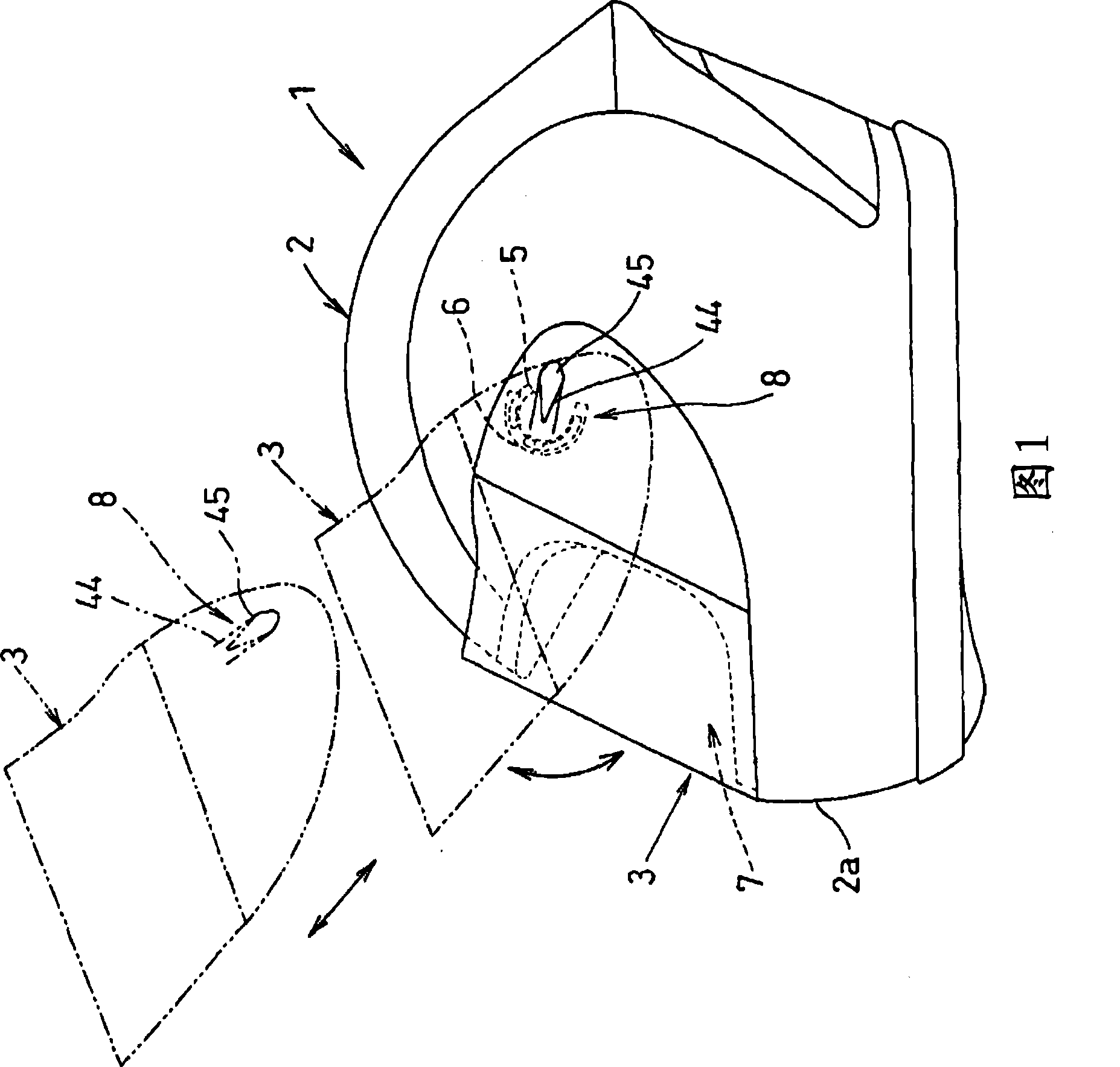
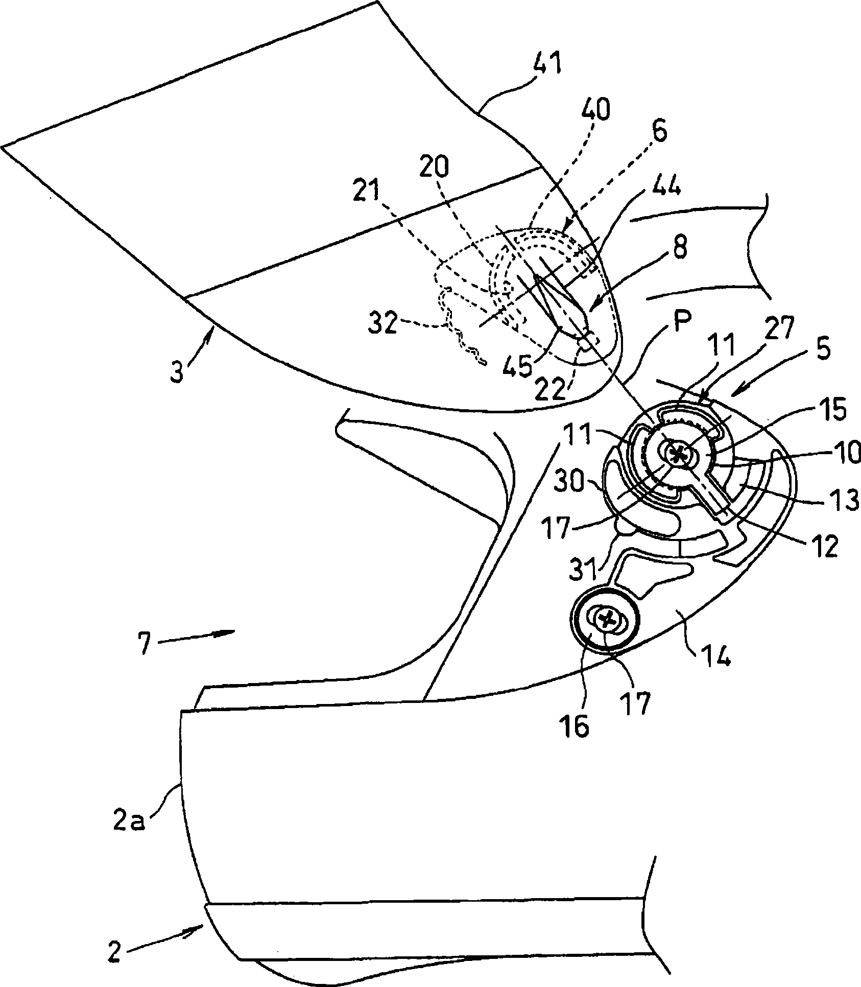
[0040] Figure 1 to Figure 5C One embodiment of the helmet 1 having the shield mounting structure of the present invention is shown. Figure 1 and figure 2 As shown, the helmet 1 has a helmet body 2 and a shield 3 covering the front of the helmet body 2 . The cover 3 is formed of, for example, carbon-containing transparent or colored transparent resin such as polycarbonate, or transparent resin treated with transflective or dimming reflective treatment.

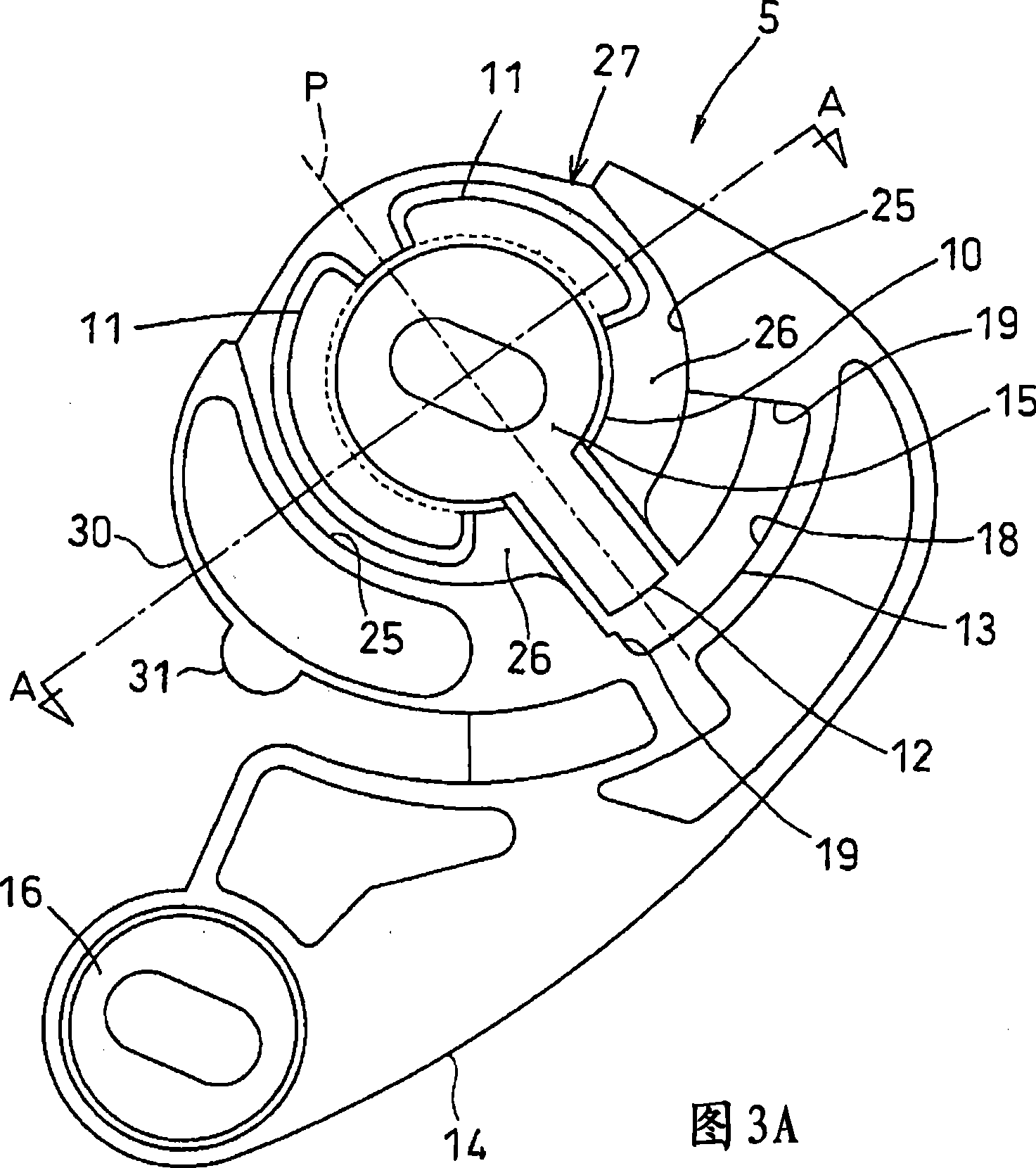
[0041] The left and right sides of the helmet body 2 are provided with rotating support parts 5, and the left and right ends of the shield 3 are provided with rotating parts 6 that are kept in a freely rotatable state and engaged with the left and right rotating support parts 5. In the engaged state of the part 5 and the rotating part 6, the shield 3 can be popped up relative to the helmet body 2 to open the helmet front, or ...


PUM


Abstract

The inventive purpose is to mount and dismount shield in the shield mounting structure rapidly and conveniently, mount helmet easily and reduce the cost. The helmet is provided with rotating supports (5) on the lateral sides of the helmet body (2) and rotating parts (6) on the lateral sides of the shield (3), through which the shield is bounced to the opening position and drawn out forwards and to the inclined top to be separated and the separated shields (3) is pressed in backwards and to the inclined bottom to be buckled, de-locking operation parts (8) arranged on the shield (3) for switching the respective rotating parts (6) and rotating supports (5) from the buckled state to the separated state only for the continuous press.

Description

technical field [0001] The invention relates to a shield installation structure of a helmet. Background technique [0002] It is common to attach a visor to a full-face helmet or the like so that an eye-exposing opening provided on the front of the helmet body can be opened and closed. The shield is a mounting structure that can be easily detached from the helmet body, so that it can be replaced when it is injured or soiled by collision with insects or pebbles during driving, or when the color or design is changed. [0003] Known as the existing mounting structure, the left and right sides of the helmet body are provided with rotating support parts, and the left and right ends of the shield are provided with rotating parts that are rotatably engaged with the left and right rotating support parts. These rotating support parts and rotating parts can be disengaged by the operation of pulling the left and right ends of the shield outward in the left and right direction relative...

Claims


Application Information

Patent Timeline
IPC IPC(8): A42B3/22
CPCA42B3/222
Inventor 村上猛
Owner OGK KABUTO
Learn More