


Quick Research
Generate reliable direction feasibility study reports for your R&D in just a few steps.

Technical Q&A
Discover and master advanced knowledge NOW. Basics, ideas, possibilities, all at once.

Find Solutions
As an expert in R&D theories, this can generate solutions to your technical problems instantly.

Evaluate Feasibility
Analyze your overall solution with one click, know your potential R&D risks in advance.

Monitor Landscape
Get weekly tech updates, stay abreast of the latest tech innovations and key insights.
Chest retraction simulating device and medical patient simulator having the device
A technology of chest, patient, applied in the field of medical simulated patient device
- Summary
- Abstract
- Description
- Claims
- Application Information
AI Technical Summary
Problems solved by technology
Method used
Image

Examples
Embodiment Construction
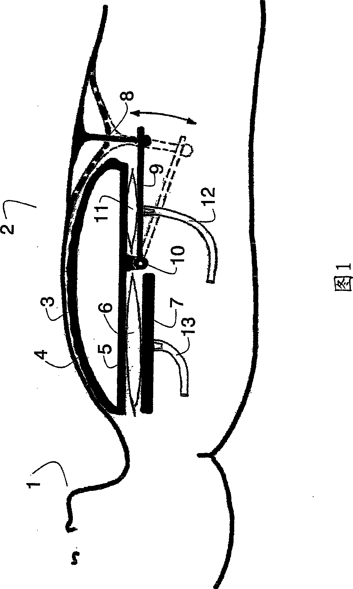
[0060] When the terms "on, above" and "below, below" are used in the following orientation, they should be read in conjunction with the drawings, in which the simulated patient device is depicted as lying supine. Other directional terms used are "down" and "up". These involved mannequins were in an upright position. The use of these terms is purely functional and serves to simplify the description of the invention and in no way imposes any limitations on the circumstances in which the invention can be applied.
[0061] FIG. 1 is a longitudinal section through a patient simulator, showing parts of a head 1 and a torso 2 . The torso 2 includes the chest skin 3 . Under the chest skin is the skeleton 4 representing the ribs and sternum. Below the framework is the first plate 5, which may also be called the upper plate. Below the plate 5 are one or preferably two lungs 6, one to the right and one to the left of the rib cage. Below the lungs 6 is a second or lower plate 7 .
...
PUM
 Abstract
Description
Claims
Application Information
 - R&D Engineer
- R&D Manager
- IP Professional
- Industry Leading Data Capabilities
- Powerful AI technology
- Patent DNA Extraction
Browse by: Latest US Patents, China's latest patents, Technical Efficacy Thesaurus, Application Domain, Technology Topic, Popular Technical Reports.
© 2024 PatSnap. All rights reserved.Legal|Privacy policy|Modern Slavery Act Transparency Statement|Sitemap|About US| Contact US: help@patsnap.com