Integral binding type bundling machine

A binding and wrapping machine technology, applied in auxiliary devices, auxiliary welding equipment, welding/cutting auxiliary equipment, etc., can solve problems such as complex procedures, hidden safety hazards, slag inclusions, and pores

Inactive Publication Date: 2009-05-27
辽宁凯尔重工集团有限公司
View PDF0 Cites 0 Cited by
  • Summary
  • Abstract
  • Description
  • Claims
  • Application Information

AI Technical Summary

Problems solved by technology

[0002] At present, due to the limitation of the wrapping machine in the production of long multi-layer wrapped high-pressure vessels, only segmental wrapping can be carried out, that is, the entire cylinder body is first decomposed into multiple barrel sections for segmental wrapping, and then combined welding of each barrel section , and finally weld the head. With this production process, the welding part must be grooved before the combined welding of each cylinder section. The process is complicated. Because there is deep circular seam welding during welding, the weld is prone to For defects such as slag inclusions and pores, it is necessary to perform flaw detection on the weld seam. In addition, due to the use of segmental wrapping, the entire inner cylinder and head cannot be tempered as a whole to eliminate welding stress and refine grains. There are potential safety hazards in bandaging high-pressure vessels

Method used


Image

  • Integral binding type bundling machine
  • Integral binding type bundling machine
  • Integral binding type bundling machine

Examples


Embodiment Construction

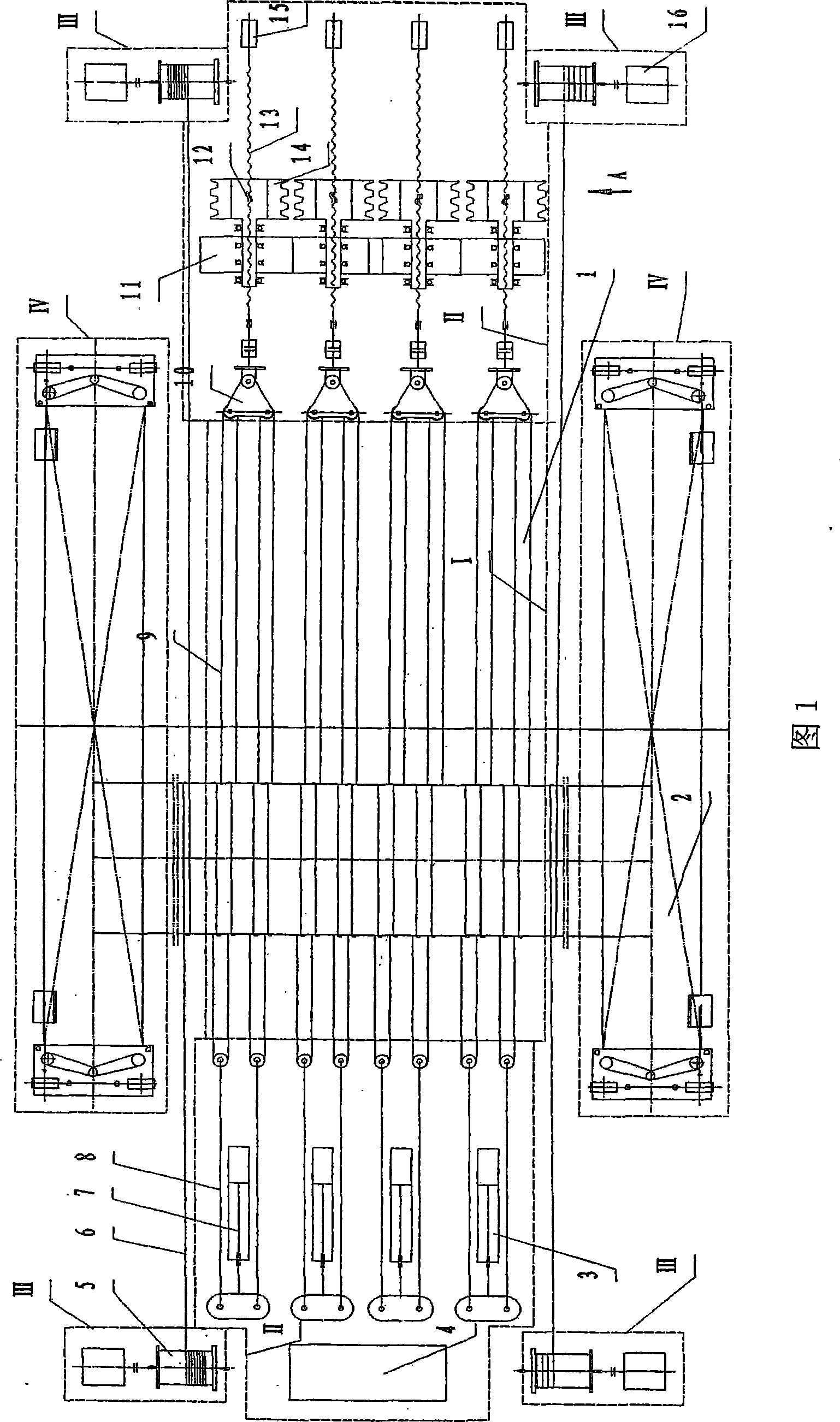
[0020] Fig. 1 shows the main body structure of the present invention, the integral binding type wrapping machine of the present invention is by wrapping workbench I, is positioned at wrapping workbench I top and is used for eliminating the wire rope tie-up mechanism II of laminate gap, makes workpiece work in wrapping The wire rope traction mechanism III for reciprocating rolling on the table and two trolleys IV located on both sides of the wrapping table can vertically lift the workpiece and move along the axial direction of the workpiece.

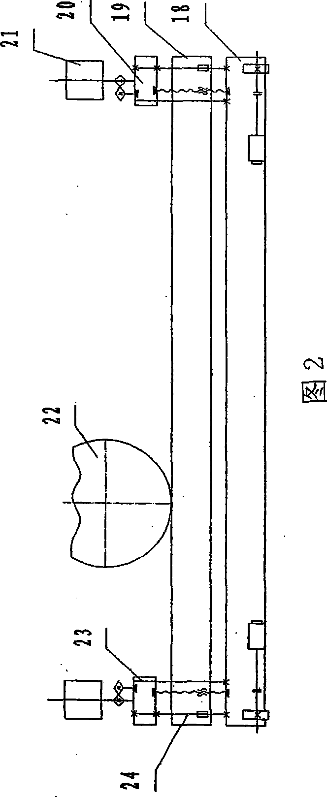
[0021] The binding workbench I is a rectangular platform 1 built by concrete, which is used to support the workpiece 22 and fix the wire rope binding mechanism II.

[0022] The wire rope tightening mechanism II is located above the binding workbench I, including the piston hydraulic cylinder 3 for pulling the wire rope, the hydraulic system 4 providing power for the hydraulic cylinder 3, the wire rope group and the pretensioning device for...


PUM


Abstract

The invention discloses an integrated binding-typed strapping machine, comprising a strapping worktable, a wirerope binding mechanism which is arranged above the binding worktable and used for eliminating the clearance of laminates, a wirerope traction mechanism which leads a workpiece to roll to-and-fro on the worktable surface and two electric lifting trolleys which are arranged at two sides of the worktable, and lead the workpiece to be vertically lifted upwards and downwards and to move axially along the workpiece. During the production process, by the operations of lifting-up, walking and falling-off, the electric lifting trolley removes the previous cylinder out of the binding worktable after the binding of the workpiece is completed and moves the next cylinder to be bound into the binding worktable so that the binding operation can be carried out; therefore, the integrated binding-typed strapping machine realizes the integrated binding to the long internal cylinder, and can carry out integrated binding of the internal cylinder which is welded with a sealing head and the welding stress of which is eliminated by backfire, and overcomes the defects that: during the segmentation binding, the quality of deep ring welding seam is difficult to be ensured, and the integrated backfire can not be carried out on the internal cylinder where the sealing head is welded so as to eliminate the welding stress.

Description

technical field [0001] The invention relates to a device for producing high-pressure containers, in particular to a wrapping device for producing multi-layer wrapped high-pressure containers. Background technique [0002] At present, due to the limitation of the wrapping machine in the production of long multi-layer wrapped high-pressure vessels, only segmental wrapping can be carried out, that is, the entire cylinder body is first decomposed into multiple barrel sections for segmental wrapping, and then combined welding of each barrel section , and finally weld the head. With this production process, the welding part must be grooved before the combined welding of each cylinder section. The process is complicated. Because there is deep circular seam welding during welding, the weld is prone to For defects such as slag inclusions and pores, it is necessary to perform flaw detection on the weld seam. In addition, due to the use of segmental wrapping, the entire inner cylinder ...

Claims


Application Information

Patent Timeline
IPC IPC(8): B23K37/00B23K37/053
Inventor 孟祥忠
Owner 辽宁凯尔重工集团有限公司
Why Eureka
Try Eureka