
Electric coiling spacing detection device

A detection device and electric roller technology, which is applied in projection devices, winding strips, door/window protection devices, etc., can solve the problems of electric roller shutter damage, inaccurate positioning, swimming, etc., and achieve reliable safety performance , The effect of reducing maintenance costs

Inactive Publication Date: 2009-05-20
JIANGSU REDLEAF AUDIO & VISUAL EQUIP
View PDF0 Cites 4 Cited by
  • Summary
  • Abstract
  • Description
  • Claims
  • Application Information

AI Technical Summary

Problems solved by technology

The disadvantage of this limit detection device is: the position of the upper and lower limit detection switches is easy to move due to the vibration in the process of transportation and handling, so that it is different from the actual upper and lower limit positions of winding objects such as screens or curtains. Corresponding, resulting in inaccurate positioning; serious damage to the electric roller shutter

Method used


Image

  • Electric coiling spacing detection device
  • Electric coiling spacing detection device
  • Electric coiling spacing detection device

Examples


Embodiment Construction

[0013] Below in conjunction with accompanying drawing, the present invention will be further described:

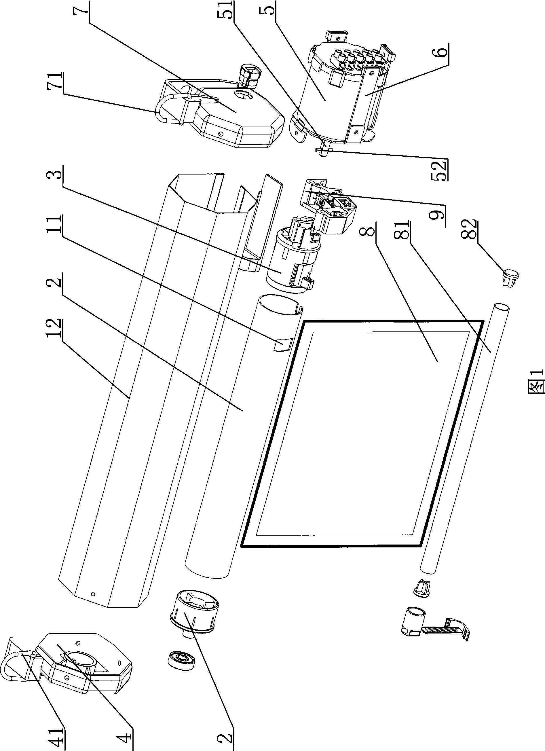
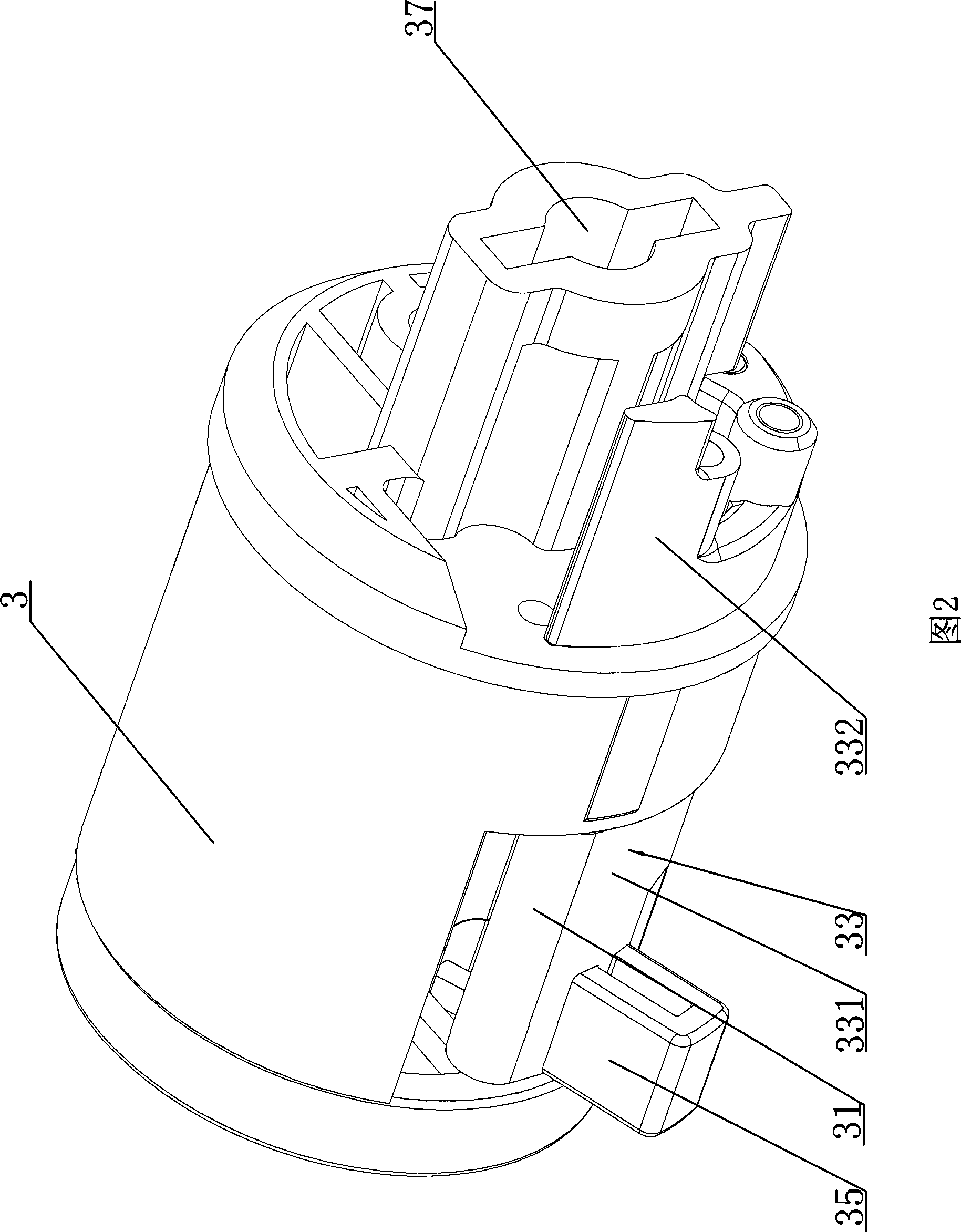
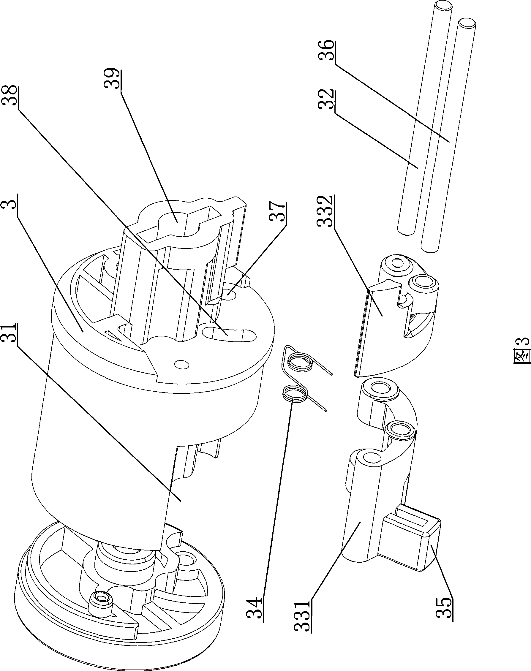
[0014] As shown in Figures 1 to 5, the electric winding limit detection device includes: a core tube 1. In actual use, the core tube 1 is installed in a casing 12, and an opening 11 is provided on the core tube 1. A core tube plug 2 and a core tube rotor 3 are respectively arranged inside the two ends of the core tube 1, and one end of the core tube 1 is movably set in the left end cover 4 through the core tube plug 2, and the other end of the core tube 1 is set through the core tube rotor 3 and the set The output shaft 51 of the synchronous motor 5 in the damping motor base 6 is connected, and the specific connection method is: the output shaft 51 of the synchronous motor 5 is fixedly arranged in the shaft hole 39 on the other end of the core tube rotor 3 through a pin shaft 52 , one end of the damping motor base 6 is fixedly arranged in the right end cover 7, one end of ...


PUM


Abstract

The invention discloses a safe and realizable electric convolute limit detection device capable of accurately positioning. The detection device comprises a core tube. The core tube is provided with an opening, the interiors of two ends of the core tube are respectively provided with a core tube plug and a core tube rotor, one end of the core tube is movably arranged in a left end cap through the core tube plug, the other end of the core tube is connected with an output shaft of a synchronous motor arranged in a vibration damping motor seat through the core tube, the vibration damping motor seat at the lower end of the core tube rotor is fixedly provided with a switch mounting seat in which an upper limit detection switch and a lower limit detection switch are respectively arranged. The limit detection device has the advantages of overcoming the defect of inaccurate positioning of the prior upper limit detection switch and the prior lower limit detection switch caused by easily moving positions, ensuring accurate of an upper limit position and a lower limit position of a convolution object, having reliable guarantee of overall safe performance at the same time, and reducing maintenance cost greatly.

Description

technical field [0001] The invention relates to a limit detection device for detecting the position of winding objects in an electric shutter. Background technique [0002] As we all know, electric roller blinds used for winding screens, curtains and other winding objects are equipped with a controller and a limit detection device. The structure of the limit detection device usually includes: a screw fixedly connected to the output shaft of the motor, The screw rod is provided with a travel nut through the thread, and the upper and lower limit detection switches are respectively arranged on both sides of the screw rod, and the positions of the upper and lower limit detection switches can be adjusted. The controller that runs the motor is connected. During production debugging, adjust the relative positions of the upper and lower limit detection switches and the stroke nut, so that the stroke between them and the stroke nut corresponds to the upper and lower strokes of windi...

Claims


Application Information

Patent Timeline
Patent Type & Authority Applications(China)
IPC IPC(8): G03B21/56E06B9/80B65H26/00
Inventor 姜国梁
Owner JIANGSU REDLEAF AUDIO & VISUAL EQUIP
Learn More