
Engine pipe laying system

A pipeline laying and engine technology, which is applied in the system field of the pipeline laying technology field, can solve complex pipeline laying and other problems, and achieve the effect of simplifying the calculation complexity and solving complex pipeline laying problems

Inactive Publication Date: 2009-05-13
SHANGHAI JIAO TONG UNIV
View PDF0 Cites 12 Cited by
  • Summary
  • Abstract
  • Description
  • Claims
  • Application Information

AI Technical Summary

Problems solved by technology

[0004] The purpose of the present invention is to overcome the deficiencies in the existing pipeline laying technology, and propose an engine pipeline laying system, which solves the shortest path problem of pipeline laying around obstacles in a shorter time according to various pipeline laying constraints, and effectively solves the complex plumbing problems

Method used


Image

  • Engine pipe laying system
  • Engine pipe laying system
  • Engine pipe laying system

Examples


Embodiment Construction

[0034] The embodiments of the present invention are described in detail below in conjunction with the accompanying drawings: this embodiment is implemented on the premise of the technical solution of the present invention, and detailed implementation methods and specific operating procedures are provided, but the protection scope of the present invention is not limited to the following the described embodiment.

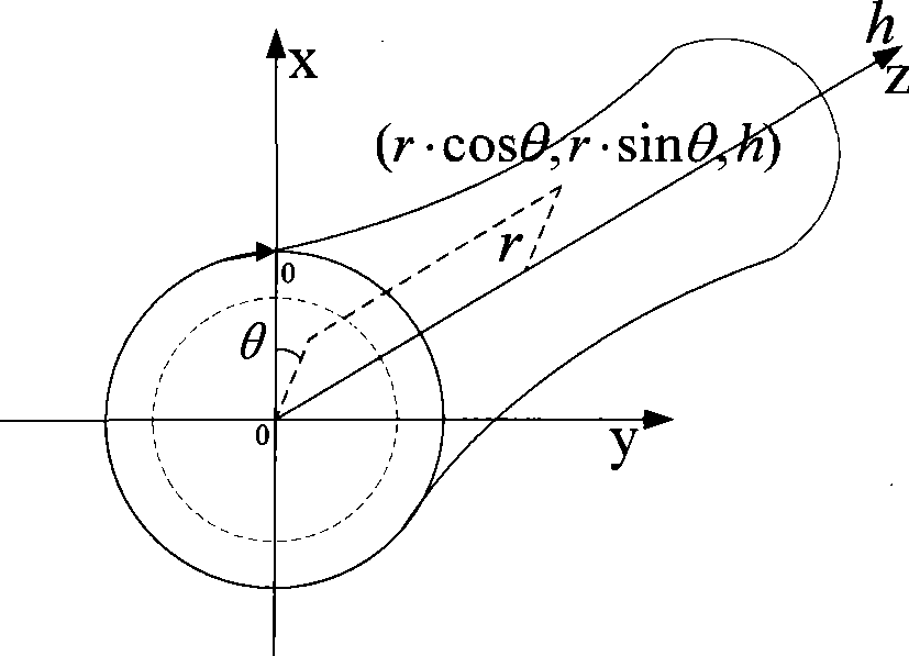
[0035] This embodiment includes: an interface module, a two-dimensional expansion module of a three-dimensional laying space, a module for identifying and sorting dense areas of pipeline laying, a module for generating a map of areas that cannot be laid, and a convex hull circumvention calculation module, wherein:

[0036] The interface module is responsible for realizing the data exchange between the engine piping system and the 3D design software. The design parameters in the 3D design software are generated into TXT text format that the engine piping system can reco...


PUM


Abstract

The invention provides an engine pipe laying system in the technical field of pipe laying. In the invention, an interface module is in charge of realizing data exchange between the engine pipe laying system and three-dimensional designing software; a two-dimensional expansion module of three-dimensional laying space is in charge of indicating three-dimensional laying space by a two-dimensional mode; an identification sequencing module of a pipe laying density area is in charge of identifying the density of the pipe laying area and setting a laying sequence of pipes; a non-laying area diagram generating module transforms conditions and restrictions for laying the pipes into a uniform visible non-laying area diagram and the uniform visible non-laying area diagram is represented on a two-dimensional expanded view; and each condition and restriction are transformed to a non-laying area on the view; a convex hull obstacle-avoiding calculation module is used to acquire a shortest path of obstacle avoiding in the non-laying area diagram by a convex hull method, and to generate a track of a pipe centerline. In the invention, the shortest pipe path bypassing the obstacle can be acquired, and the existing computational complexity of engine pipe laying is simplified.

Description

technical field [0001] The invention relates to a system in the technical field of pipeline laying, in particular to an engine pipeline laying system. Background technique [0002] There are hundreds of conduits and cables and various types of clamps outside the engine, and the spatial orientation of the conduits is very complicated, so the piping work is very complicated. And because of the integration of all engine components, it is very difficult to determine the space curve of the duct. When laying pipes, the minimum distance requirements between conduits and conduits, conduits and accessories, and restrictions on the external dimensions of the engine should be considered. At present, engine pipeline laying still mainly relies on the artificial knowledge, experience and even intuition of designers, and the test method of trial-manufacturing metal prototypes is used to verify the results of pipeline laying, and the workload is heavy. The engine piping system design is d...

Claims


Application Information

Patent Timeline
IPC IPC(8): G06F17/50
Inventor 殷跃红周晨王承恩
Owner SHANGHAI JIAO TONG UNIV
Learn More