
Electronic apparatus and method for controlling three phase current point switch

A technology of three-phase AC and electronic devices, which is applied in the direction of electrical equipment, transportation and packaging, railway car body parts, etc. used to manipulate turnouts or line breakers, and can solve the problems of prolonging the construction period, poor scalability, and a large number of relay circuits Wiring and other problems, to achieve the effect of convenient system composition, elimination of hidden dangers of accidents, and quick troubleshooting

Active Publication Date: 2009-05-13
兰州大成科技股份有限公司
View PDF0 Cites 18 Cited by
  • Summary
  • Abstract
  • Description
  • Claims
  • Application Information

AI Technical Summary

Problems solved by technology

This switch position monitoring method has no safety problems under normal circumstances, but during station construction or equipment maintenance, engineers and technicians often add indicating diodes to both the positioning position and the reverse position for the convenience of testing and finding faults. When the fixed operation command is executed, no matter what position the switch machine is in, the switch is considered to be in the positioning position because the external circuit has been formed. Similarly, after the reverse operation command is executed, no matter what position the switch machine is in, it is considered The turnout is in the reverse position, which constitutes a false position representation, causing a very large safety hazard to the actual operation
[0006] 2. Poor maintainability
[0007] 3. Poor scalability
When the system needs to be expanded or modified, the relay circuit needs a lot of wiring, which increases the failure rate on the one hand, and prolongs the construction period on the other hand, affecting the use efficiency

Method used


Image

  • Electronic apparatus and method for controlling three phase current point switch
  • Electronic apparatus and method for controlling three phase current point switch
  • Electronic apparatus and method for controlling three phase current point switch

Examples


Embodiment 1

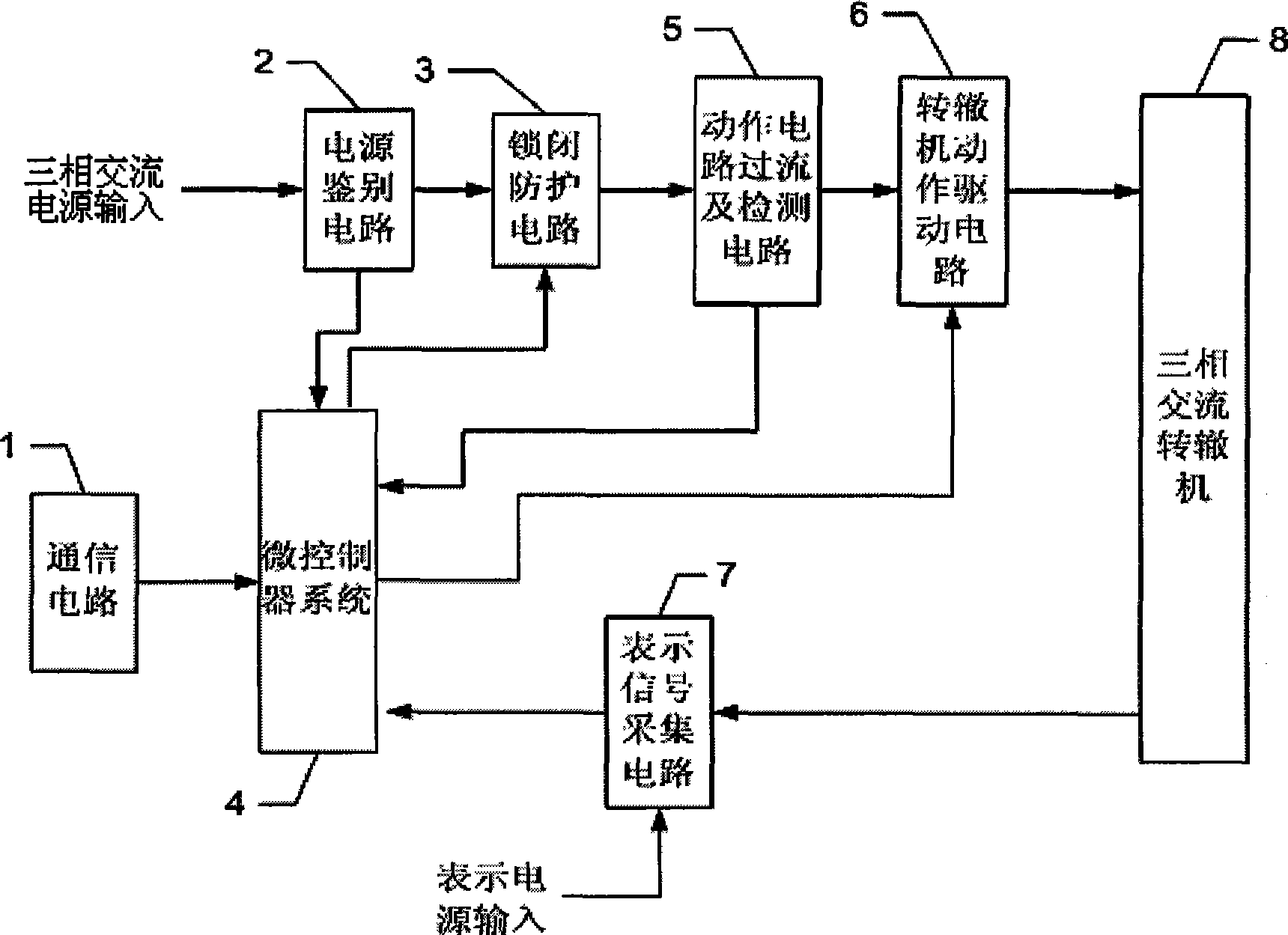
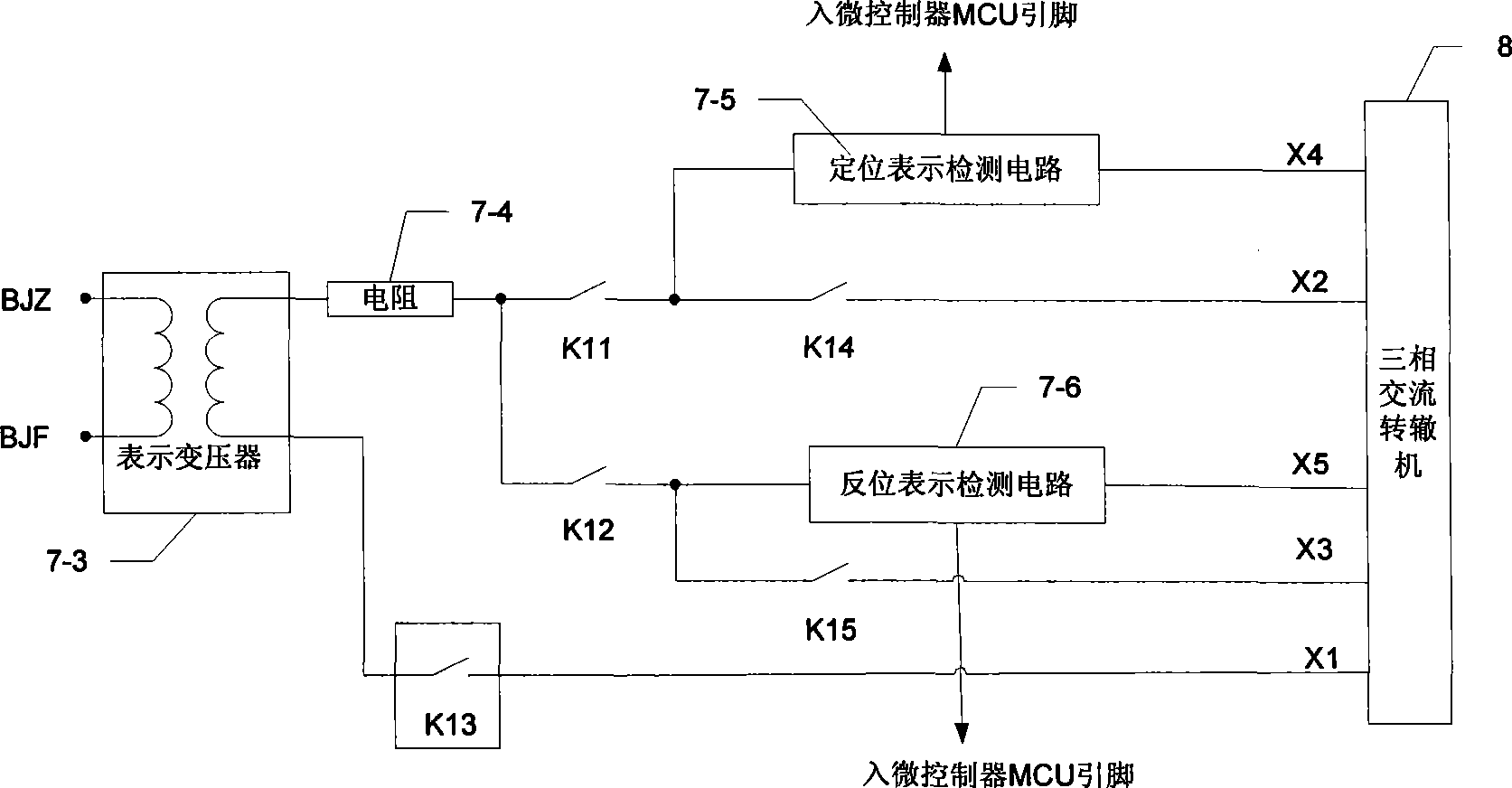
[0035] Example 1, see figure 1, an electronic device for controlling a three-phase AC switch machine, including a locking protection circuit 3, and a three-phase AC action power input power identification circuit 2, the output end of which is connected to the locking protection circuit 3 and the action circuit in sequence The overcurrent and detection circuit 5, the switch machine action drive circuit 6 to drive the three-phase AC switch machine 8; the output terminal of the three-phase AC switch machine 8 is connected to the signal acquisition circuit 7; the communication circuit 1, the power identification circuit 2, The output end of the action circuit overcurrent and detection circuit 5 and the signal detection circuit 7 are connected to the input end of the microcontroller system 4; the output end of the microcontroller system 4 is provided with a locking protection circuit 3 and a switch machine action drive circuit 6 ; Indicate that the input terminal of the signal dete...

Embodiment 2

[0042] Example 2, see figure 2 , the described power identification circuit 2 includes the input terminals of resistors 2-1, 2-3 and voltage sensors 2-2, 2-4 connected between AB and BC of the three-phase power supply, and the voltage sensors 2-2, 2-4 The output terminal of 4 is connected to the AD pin line of the microcontroller system 4 after the real-time acquisition and conversion of the voltage of the operational amplifiers 2-5 and 2-6 into digital signals. The controller calculates the phase voltage and judges whether the phase sequence is correct according to the digital / analog conversion value.

Embodiment 3

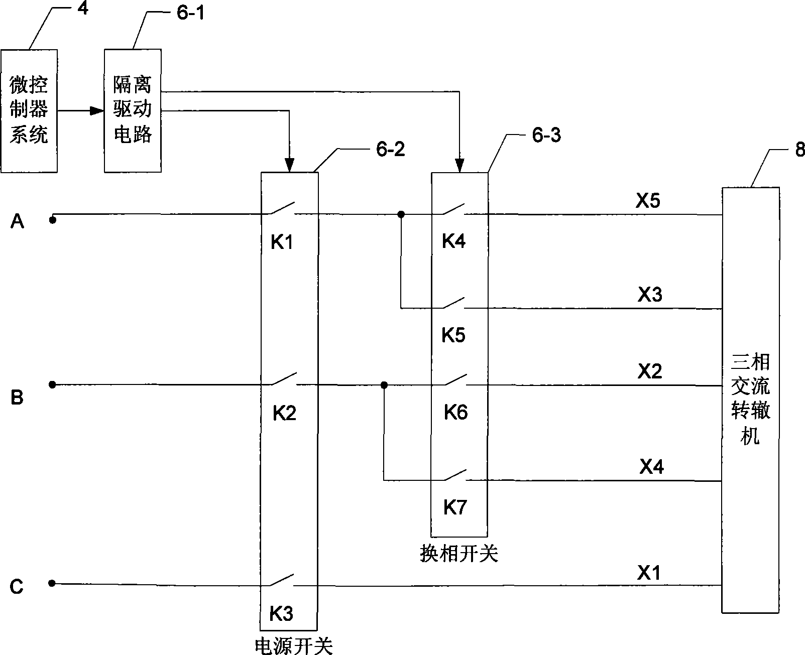
[0043] Example 3, see image 3 , an electronic device for controlling a three-phase AC switch machine, the switch machine action drive circuit 6 includes an isolated drive circuit 6-1 at the output end of the microcontroller system 4, and an isolated drive circuit 6-1 at the output end of the microcontroller system The output terminal of 6-1 is provided with power switches K1, K2, K3 and reversing switches K4, K5, K6, K7 respectively connected with the three-phase power supply, among which reversing switches K4, K5 are electrically connected with power switch K1, reversing The switches K6, K7 are electrically connected to the power switch K2; the power switches K1, K2 are respectively connected to the three-phase AC switch machine 8 input terminals X5, X3, X2, X4, X1 is electrically connected. When the three-phase AC point machine turns in 8 directions, the power switches are all closed, and K4 and K6 in the reversing switch are closed; Regardless of whether it is rotating t...


PUM


Abstract

The invention mainly relates to an automatic control system for transportation railway signals, in particular to an electronic device for controlling a three-phase alternating current point machine and the method thereof. The electronic device comprises a locking protection circuit (3), and is characterized in that the device further comprises a discriminate circuit (2) for the input power supply of a three phase operation power supply; the locking protection circuit (3), an actuating circuit overflowing and detecting circuit (5), and a point machine action driving circuit (6) is sequentially connected to the output end of the discriminate circuit for driving a three-phase alternating current point machine (8); the output end of the three-phase alternating current point machine (8) is connected with an indicating signal acquisition circuit (7); the output ends of a communication circuit (1), the power supply discriminate circuit (2), the actuating circuit overflowing and detecting circuit (5) and the output end of the indicating signal acquisition circuit (7) are connected with the input end of a microcontroller system (4); the locking protection circuit (3) and the point machine action driving circuit (6) are arranged at the output end of the microcontroller system (4); and the indicating power supply input is arranged at the input end of the indicating signal detection circuit (7). The invention adopts non-contact control technique, and a switch converting indicating circuit formed by a safe relay is replaced by an electronic circuit.

Description

Technical field: [0001] The invention mainly relates to an automatic control system for traffic and transportation railway signals. Background technique: [0002] With the demand of "high speed and heavy load" in railway transportation, a large number of three-phase AC switching devices are used. For the control circuit of this device, whether it is electrical centralized interlocking or computer interlocking, it adopts logic control composed of relays. circuit to achieve. This relay circuit has the following problems: [0003] 1. There are hidden dangers in safety. [0004] (1) The relay circuit is composed of separate components and relays. The contact control technology of the relay is used. It is easy for ordinary technicians to change the control logic by sealing the connection points, and there are great hidden dangers in safety. [0005] (2) The indicating circuit composed of relays can only monitor the signal of one position in the same period of time, that is, wh...

Claims


Application Information

Patent Timeline
IPC IPC(8): B61L5/06
Inventor 范多旺魏宗寿方亚非何涛邢东峰陈光武魏文军旷文珍牛宏侠
Owner 兰州大成科技股份有限公司
Learn More