
Secondary clamping board device for electrical power system relay protection

A technology of relay protection and secondary pressure plate, applied in emergency protection circuit devices, circuits, electric switches, etc., can solve the problem that the operator cannot fundamentally prevent the operator from walking in the wrong interval and misoperation, and achieves convenient and reliable use and simple structure. , The effect of preventing misuse accidents

Active Publication Date: 2009-05-06
STATE GRID CORP OF CHINA +2
View PDF0 Cites 15 Cited by
  • Summary
  • Abstract
  • Description
  • Claims
  • Application Information

AI Technical Summary

Problems solved by technology

[0003] The anti-misoperation measures for the secondary pressure plate generally only take some measures in operation management, such as standard double naming of the secondary pressure plate for relay protection, color code management, and installation of anti-mis-touch covers, but these measures can only To remind the operator to a certain extent, it is impossible to fundamentally prevent the operator from taking the wrong interval or reversing the order of operations and causing misoperation
It can be said that technically the current secondary platen has no effective anti-misoperation measures.

Method used


Image

  • Secondary clamping board device for electrical power system relay protection
  • Secondary clamping board device for electrical power system relay protection
  • Secondary clamping board device for electrical power system relay protection

Examples


Embodiment Construction

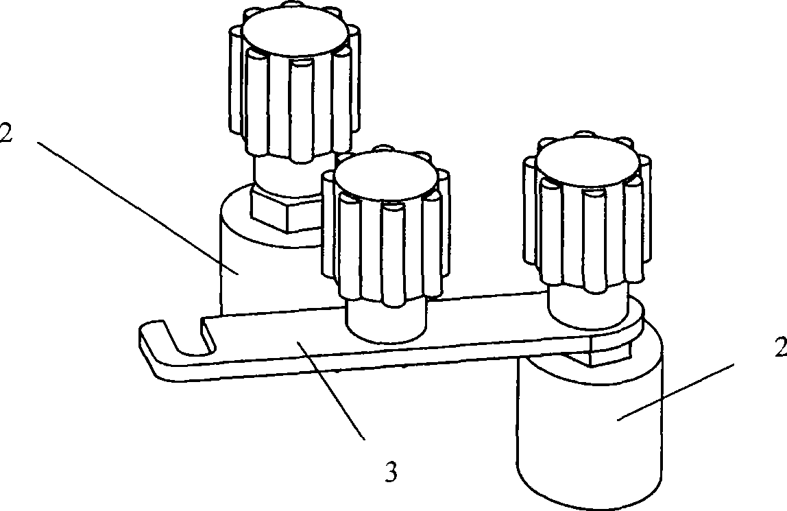
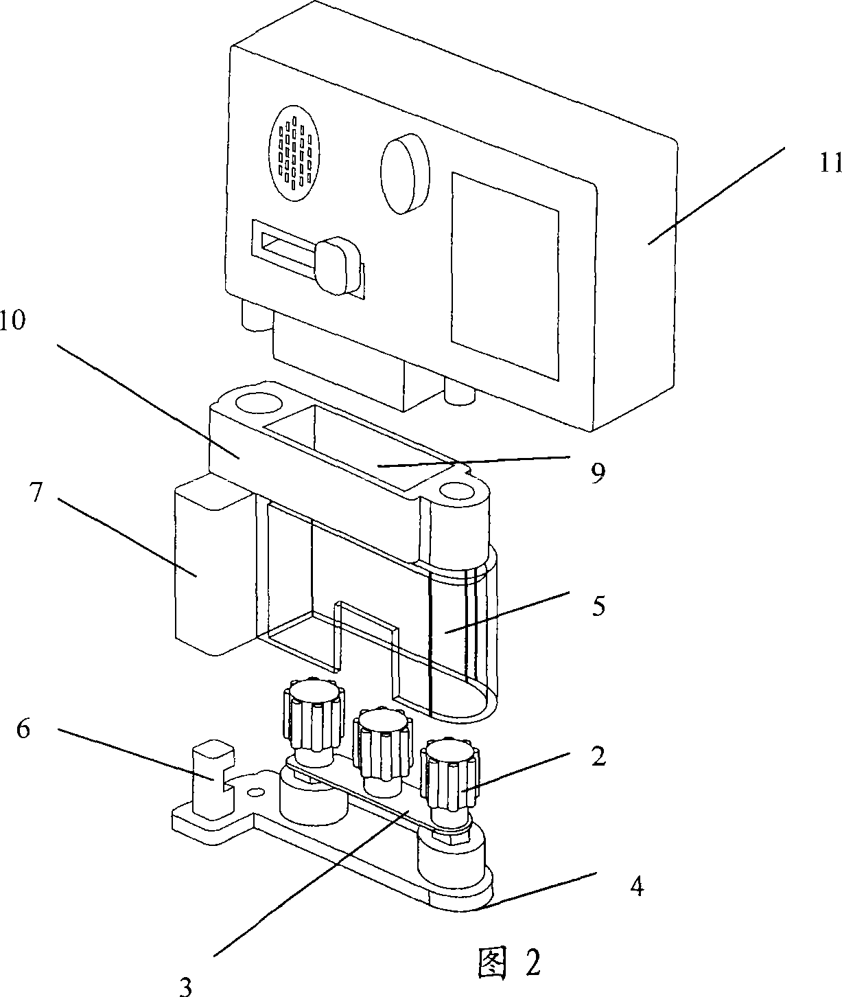
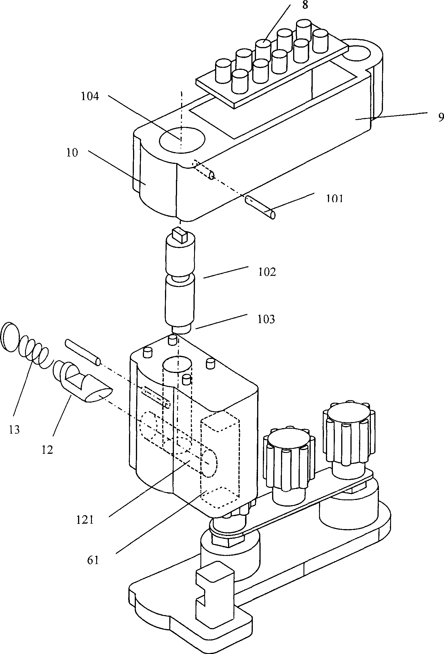
[0012] The present invention will be described in detail below in conjunction with the accompanying drawings: As shown in Figures 2 and 3, the present invention mainly includes a pressing plate consisting of adjacently arranged pressing plate connecting columns 1, pressing plate columns 2 and connecting pressing plate 3 between the two. Main body, the main body of the pressing plate is placed on a pressing plate seat 4, and the pressing plate seat 4 is equipped with a pressing plate cover 5 that can cover the pressing plate main body. The matching anti-mistake lock body 7 of the lock catch 6.

[0013] The upper part of the pressure plate cover body 5 is provided with an anti-mislocking anti-mislocking frame 9 with a locking code plate 8, and one side thereof is provided with an anti-mislocking head 10 matched with the anti-misoperation lock body 7.

[0014] The anti-mislocking code frame 9 is equipped with a microcomputer anti-misoperation unlocking key 11, which is a prior ar...


PUM


Abstract

The invention relates to a relay protection secondary pressure plate device for an electric power system. The relay protection secondary pressure plate device mainly comprises a pressure plate connecting column and a pressure plate column which are adjacently arranged, and a pressure plate main body formed by pressure plates connected between the pressure plate connecting column and the pressure plate column, wherein the pressure plate main body is placed on a pressure plate seat, a pressure plate cover body for covering the pressure plate main body is matched on the pressure plate seat, and an anti-malfunction locking body matched with a lock catch arranged on the pressure plate seat is arranged on the pressure plate cover body; an anti-malfunction locking code pairing frame with a lock code plate is arranged at the upper part of the pressure plate cover body, and an anti-malfunction locking head matched with the anti-malfunction locking body is arranged at one side of the pressure plate cover body; and the invention has simple structure and convenient and reliable use, can effectively prevent the incorrect manipulation accident of the secondary pressure plate in the electric power system, solves the problem the electric power system only has primary equipment for anti-malfunction and does not take reliable secondary anti-malfunction measures for long term, extends the application field of the anti-misoperation system of the microcomputer, improves the investment efficiency and especially provides assurance for safe operation of the electric network.

Description

technical field [0001] The invention relates to a secondary pressing plate device for controlling the input and exit of a relay protection device or changing the operation mode in secondary equipment of a power system, which belongs to a relay protection operation device. Background technique [0002] The relay protection device in the secondary equipment of the power system is the basic equipment to ensure the safe operation of the power primary equipment. By operating the secondary pressure plate of the relay protection, the input and exit of the protection device can be controlled, or the operation mode of the protection device can be changed. The misoperation of the secondary pressure plate may cause the power primary equipment to lose protection and endanger the safe operation of the power grid. At present, the form of pressing plate generally used in the secondary pressing plate, such as Figure 1 As shown, it includes the adjacently arranged pressure plate connecting ...

Claims


Application Information

Patent Timeline
IPC IPC(8): H02H7/26H01H9/20H01H9/26
Inventor 潘建乔钱国良潘白浪张健张凯俊吴韬
Owner STATE GRID CORP OF CHINA
Learn More