Microswitch

A technology of micro switch and movable mechanism, which is applied in the direction of electric switches, electrical components, circuits, etc. It can solve the problems of low rated current of the switch, slow connection and disconnection speed, unstable electric repulsion, etc., and achieve the switching function Sensitive action, quick connection and disconnection, avoiding the effect of high heat generation

Inactive Publication Date: 2011-11-23
ZHEJIANG ZHONGXUN ELECTRONICS
View PDF0 Cites 0 Cited by
  • Summary
  • Abstract
  • Description
  • Claims
  • Application Information

AI Technical Summary

Problems solved by technology

[0003] 1. During the working process of the switch, due to the contact position of the fulcrum contact with the action of the button, the "line-surface-line" or "surface-line-surface" contact occurs, so the shrinkage of the current line exists. The phenomenon of sudden change leads to unstable electric repulsion, unreliable contact at the fulcrum, high heat generation, high temperature of the switch, and the switch will be burnt due to the melting of the base and base cover due to excessive temperature rise;
[0004] 2. Due to the line surface change of the contact position of each fulcrum, the switch function is insensitive, the speed of connection and disconnection is slow, the arcing time is long, and the life of the switch is short
[0005] 3. The heat dissipation of the switch only depends on the heat conduction of each part to radiate heat to the air through the surface, and the heat dissipation speed is slow, and another convection method with a faster heat dissipation speed is not used on the micro switch
[0006] 4. The positioning groove of the contact bridge on the second bend is formed by upsetting, the size is unstable, the required pressure is high, and the punch wears a lot
[0007] 5. Due to the change of the line surface of the contact position of each twisting point, the current is unstable, so that the rated current of the switch is not high, and it cannot switch the electric current above 18A.

Method used


Image

  • Microswitch
  • Microswitch
  • Microswitch

Examples


Embodiment Construction

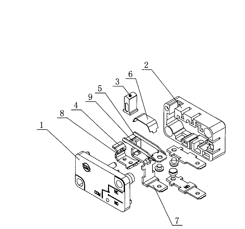
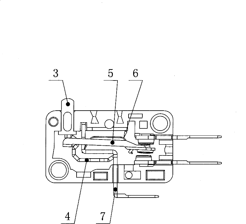
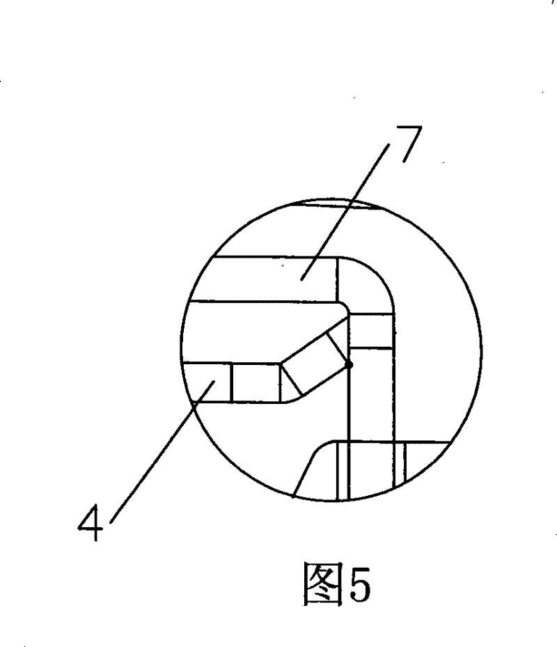
[0030] like figure 1 , figure 2 , image 3 , Figure 4 , Figure 5 , Image 6 , Figure 7 , Figure 8 , Figure 9 , Figure 10 , Figure 11 , Figure 12 , Figure 13 , Figure 14 , Figure 15 , Figure 16 As shown, the micro switch provided by the present invention includes a base cover 1 and a base 2, and the base cover 1 and the base 2 are provided with a switch function conversion mechanism, and the function conversion mechanism includes a button 3, a two-bend 4, a contact bridge 5. The reed 6 and the three bends 7 and the two bends 4 are provided with a contact bridge positioning groove 8. The contact bridge positioning groove 8 is directly bent and formed by the two bends. The contact bridge 5 is provided with a mounting groove 9. The fulcrums between the bend 4 and the contact bridge 5 and between the double bend 4 and the triple bend 7 are always in line contact. In this embodiment, the end of the second bend 4 in contact with the triple bend 7 is bent u...


PUM


Abstract

The invention discloses a microswitch which comprises a basal cover and a base, wherein a function conversion moving mechanism of the switch is arranged in the basal cover and the base, and the function conversion moving mechanism comprises a button, a double bend, a contact bridge, a reed and a triple bend, wherein a contact bridge positioning groove is arranged on the double bend, a mounting groove is arranged on the contact bridge, and the linear contact is adopted between the double bend and the contact bridge as well as between the double bend and the triple bend. In the invention, as the linear contact is adopted between the double bend and the contact bridge of the microswitch as well as between the double bend and the triple bend, the contact areas among all hinged fulcrums alwaysdo not change, and the flowing current is more constant, thereby high temperature rise of the switch caused by large heat productivity as the current increases suddenly is avoided; in addition, the switch function action is more sensitive as the linear contact is always adopted among all hinged fulcrums of the switch, the connecting and disconnecting speed of the switch is accelerated, the arc time is shorter, and the service life of the switch can be prolonged.

Description

technical field [0001] The present invention relates to a micro switch, especially an appliance switch suitable for actuating or controlling household or similar electrical appliances and other equipment operated by an operating member or by exciting a transmission member. Background technique [0002] At present, the functional structure of the micro switch is composed of buttons, two bends, three bends, contact bridge components, reeds, and straight end components. When the button is pressed down or released after a certain distance, The switch realizes the conversion of kinetic energy. During the operation of the switch, the two bends rotate around the twisted fulcrum in contact with the three bends when the button is pressed, and the contact bridge rotates around the twisted fulcrum in contact with the two bends. The switch is in action During the process, the contact at the fulcrum is the contact mode of "line-surface-line" or "surface-line-surface", and this micro swit...

Claims


Application Information

Patent Timeline
Patent Type & Authority Patents(China)
IPC IPC(8): H01H13/52H01H13/36H01H13/10
Inventor 郑建中田学会
Owner ZHEJIANG ZHONGXUN ELECTRONICS
Why Eureka
Try Eureka