
Mobile portable swing machine

A lifting machine and portable technology, applied in the direction of cranes, etc., can solve the problems that the handling equipment cannot be installed and used, is inconvenient to install and use, and the space is small, and achieves the effect of compact structure, easy operation, and convenient portability

Inactive Publication Date: 2009-05-06
山西实普瑞吊运机制造有限公司
View PDF0 Cites 8 Cited by
  • Summary
  • Abstract
  • Description
  • Claims
  • Application Information

AI Technical Summary

Problems solved by technology

However, most of the existing handling devices or lifting equipment are cumbersome and inconvenient to install and use.
In some places, due to the small space, the existing handling equipment cannot be installed and used at all.

Method used


Image

  • Mobile portable swing machine
  • Mobile portable swing machine

Examples


Embodiment Construction

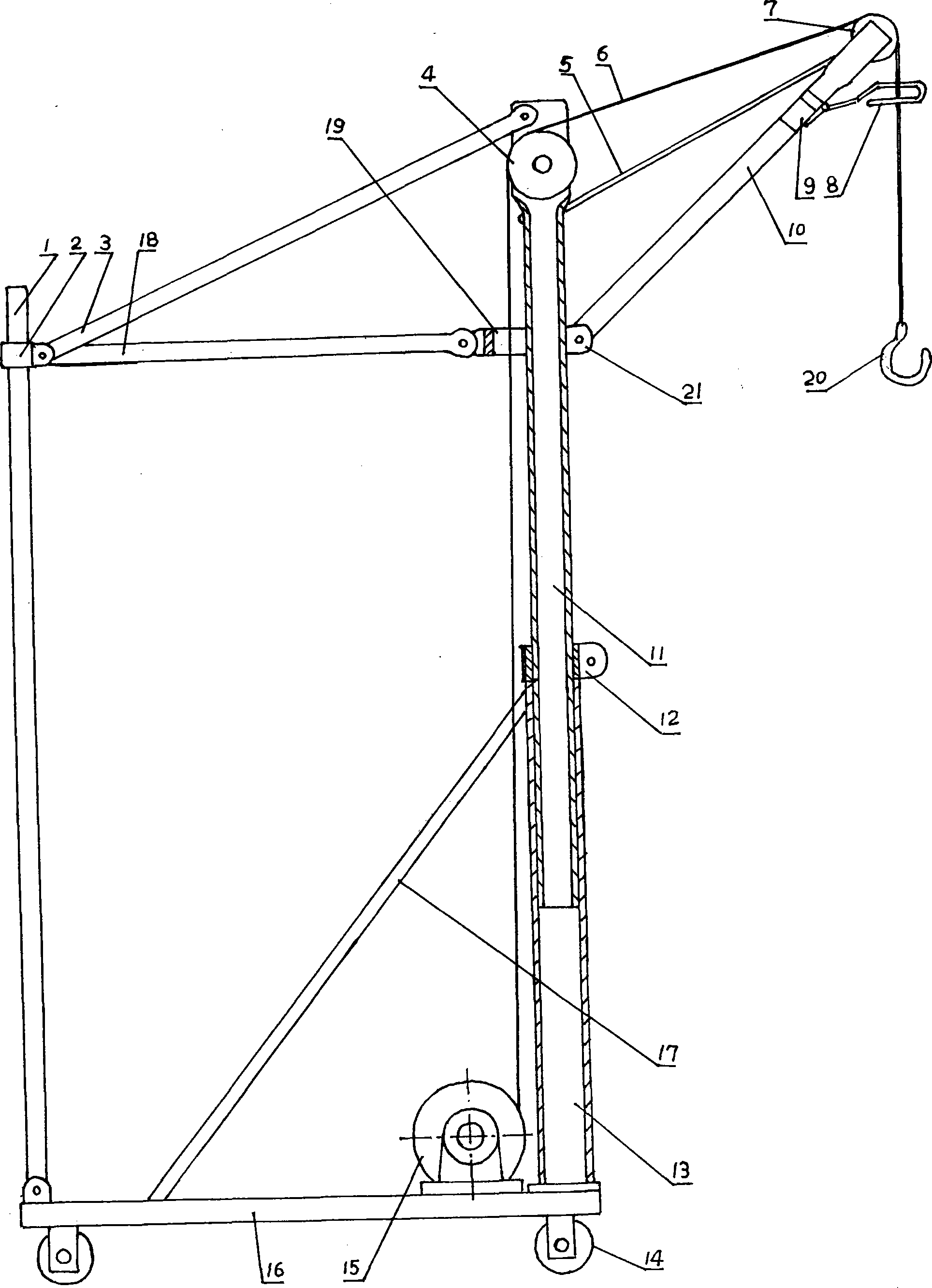
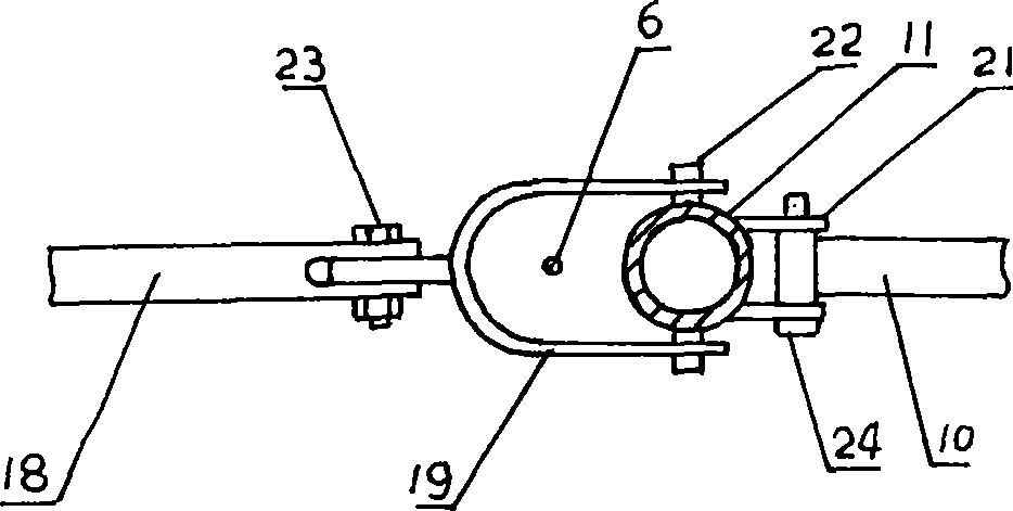
[0011] The upright rod 13 is fixed on the front end of the base 16, and the host part 15 is mounted on the base 16 near the front end. The telescopic pole 11 is inserted into the pole 13 . The clamp 12 is sleeved on the outside of the telescopic pole 11 and stuck on the upper end of the pole 13 . During use, the upper and lower positions of the telescopic pole 11 can be adjusted through the clamp 12 according to the site and the conditions of the articles, so as to fix the height of the arm 10 . The lower end of the arm 10 is mounted on the ear 21 at the middle part of the telescopic vertical rod 11 by a pin 24 . Be provided with limit frame 8 and travel switch 9 near pull arm rope 5 places in arm 10 front section, promptly pull travel switch 9 and cut off power supply after heavy object bumps into limit frame 8, prevents from hoisting and over-positioning.

[0012] The lower end of the auxiliary vertical rod 1 is mounted on the rear end of the base 16 through a bolt, and th...


PUM


Abstract

The invention provides a movable portable hoisting machine applicable to the hoisting or lowering of articles, with the purpose of wide applicable range and convenient carrying. The movable portable hoisting machine comprises a host machine part and a bracket; the host machine part comprises a motor, a reducer, a clutch, a brake, a rope cylinder, and a wire rope; the bracket comprises a base, a vertical rod, a telescopic vertical rod, an auxiliary vertical rod, pulling rods, a pulley, an arm and a binding clasp; the upper end of the telescopic vertical rod is provided with the pulley and the upper pulling rod, the middle part thereof is provided with a lug or a through hole which is used for installing the arm and the middle pulling rod, and the lower part thereof is inserted into the vertical rod; the external surface of the telescopic vertical rod is provided with the binding clasp; the rear end of the arm is arranged on the telescopic vertical rod and the front end thereof is provided with the pulley; a pulling arm rope is arranged closely to the pulley; the other end of the pulling arm rope is sleeved on the telescopic vertical rod; the sleeve is arranged above the lug; the vertical rod is fixed at the front end of the base; the auxiliary vertical rod is fixed at the rear end of the base; the auxiliary vertical rod and the telescopic vertical rod as well as the vertical rod and the base are fixedly connected with each other through the pulling rod; the lower surface of the base is provided with a wheel; and the host machine part is arranged at the front end of the base.

Description

technical field [0001] The invention relates to a portable hoisting device used for building decoration or workshop production and warehouse management. Background technique [0002] In engineering construction such as building decoration or waterproofing, various construction materials often need to be moved up and down or horizontally. In workshop production and warehouse management, various workpieces and items also need to be transported up and down or horizontally. However, most of the existing handling devices or lifting equipment are cumbersome and inconvenient to install and use. In some places, due to the small space, the existing handling equipment cannot be installed and used at all. Contents of the invention [0003] The purpose of the present invention is to overcome the deficiencies of the above-mentioned prior art, and to provide a mobile and portable hoist that has a wide application range, is easy to carry, and is safe and convenient. [0004] The prese...

Claims


Application Information

Patent Timeline
Patent Type & Authority Applications(China)
IPC IPC(8): B66C23/48B66C23/62B66C23/90
Inventor 刘春雨刘春山
Owner 山西实普瑞吊运机制造有限公司
Learn More