Refrigerated container underframe structure and refrigerated container using the under-frame structure

A technology for refrigerated containers and underframes, which is applied in packaging, transportation and packaging, transporting passenger cars, etc., which can solve the problems of high foaming density of the foam layer, high consumption of foaming materials, and high material consumption, etc., to reduce the foaming density , reduce the heat leakage rate, reduce the effect of consumption

Active Publication Date: 2009-05-06
TAICANG CIMC REEFER LOGISTICS EQUIP CO LTD +2
View PDF0 Cites 11 Cited by
  • Summary
  • Abstract
  • Description
  • Claims
  • Application Information

AI Technical Summary

Problems solved by technology

The bottom beam structure is welded with the bottom side beam at both ends of each bottom beam to form a rigid whole. In order to meet the ISO test of refrigerated containers, the bottom beams are closely arranged and the number is large. The weight of the goods in the box is carried by the foam layer first. , and then passed to the bottom beam, this kind of structure consumes a lot of materials
The corrugated plate chassis structure is welded by two longitudinal bottom side beams and 2 to 3 bottom beams. This structure mainly uses corrugated sub-floors to replace the load bearing of the bottom beams. In order to meet the ISO test of refrigerated containers, corrugated plates are required It can bear most of the load, its waveform is high, and it is easy to be damaged by debris on the ground, and the foaming density of the foam layer is relatively high, the consumption of foam material is large, and the heat leakage rate is also large

Method used


Image

  • Refrigerated container underframe structure and refrigerated container using the under-frame structure
  • Refrigerated container underframe structure and refrigerated container using the under-frame structure
  • Refrigerated container underframe structure and refrigerated container using the under-frame structure

Examples


Embodiment Construction

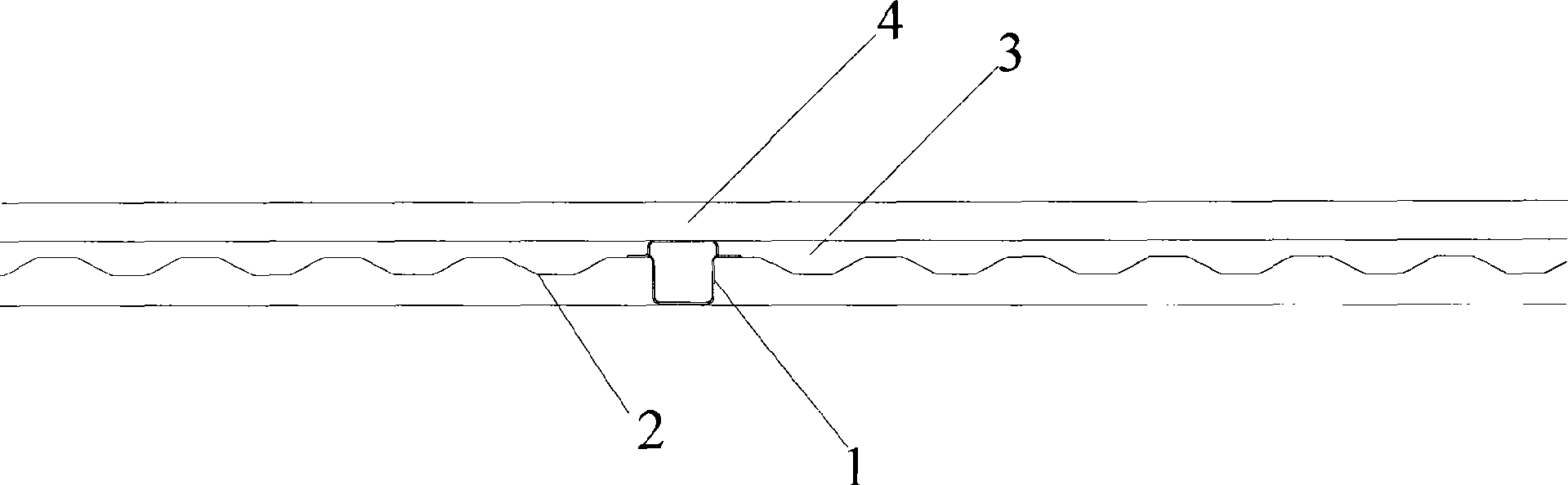
[0019] The present invention provides an underframe structure for a refrigerated container, which includes two bottom side beams 7 arranged longitudinally, a plurality of main bottom beams 1 vertically arranged on the bottom side beams, and the bottom side beams 7 and main The corrugated auxiliary floor 2 connected to the bottom beam 1, the two ends of the main bottom beam 1 are welded on the bottom side beam 7, the corrugated auxiliary floor 2 is placed on the main bottom beam, and it is characterized in that it also includes multiple small bottoms Crossbeams 5, each small bottom crossbeam 5 is placed between the trough of the corrugated sub-floor 2 and the T floor 4 in the box, and its two ends are also vertically welded on the bottom side beam 7.

[0020] Such as figure 2 As shown, in Embodiment 1 of the present invention, the underframe structure of the refrigerated container is mainly composed of two longitudinal bottom side beams 7 and multiple main bottom cross beams 1...


PUM


Abstract

The invention provides a chassis structure used for a refrigerated container, comprising two vertically-arranged bottom side beams, a plurality of main bottom cross beams which are arranged to be vertical to the bottom side beams and a corrugated sub floor which is connected with the bottom side beams and the main bottom cross beams. Two ends of the main bottom cross beam are welded onto the bottom side beams and the corrugated sub follow is arranged on the main bottom cross beams. The invention is characterized in that the structure also comprises a plurality of small bottom cross beams and each small bottom cross beam is arranged between the trough of the corrugated sub floor and a T floor inside the container and two ends of the small bottom cross beam are also vertically welded onto the bottom side beams. The invention also provides a refrigerated container adopting the chassis structure. For the chassis structure of the invention, the weight of goods inside the container is mainly borne by the main bottom cross beams and the small bottom cross beams so as to reduce the bearing strength of the corrugated sub floor and enhance the rigidity and strength of the chassis of the refrigerated container, and simultaneously to reduce the corrugated sub floor materials and corrugated height and the foam density of a foam layer so as to reduce the consumption of structure materials and foam material and reduce the heat-leakage rate.

Description

technical field [0001] The invention relates to a refrigerated container, in particular to an underframe structure of the refrigerated container. Background technique [0002] The underframe structure, foam layer and floor of the refrigerated container together form the load-bearing structure of the goods in the box. The underframe structure of the refrigerated container has experienced the development from the bottom beam structure to the corrugated underframe structure. The bottom frame of the refrigerated container is mainly composed of two longitudinal bottom side beams and multiple bottom beams. The bottom beam structure is welded with the bottom side beam at both ends of each bottom beam to form a rigid whole. In order to meet the ISO test of refrigerated containers, the bottom beams are closely arranged and the number is large. The weight of the goods in the box is carried by the foam layer first. , and then passed to the bottom beam, this kind of structure consumes ...

Claims


Application Information

Patent Timeline
Patent Type & Authority Applications(China)
IPC IPC(8): B65D90/02B65D88/74
Inventor 宋卫国杨维廷
Owner TAICANG CIMC REEFER LOGISTICS EQUIP CO LTD
Why Eureka
Try Eureka