
Automatic experiment system for bridge type crane

An overhead crane and experimental system technology, applied in educational appliances, instruments, teaching models, etc., can solve the problems of high labor intensity, high skill requirements for crane operators, and inability to achieve safe operation of the crane system, and achieve convenient data processing. , The effect of large measurement range and low price

Inactive Publication Date: 2009-04-29
NANKAI UNIV
View PDF0 Cites 13 Cited by
  • Summary
  • Abstract
  • Description
  • Claims
  • Application Information

AI Technical Summary

Problems solved by technology

[0005] Generally speaking, in order to realize the safe operation of the crane system, the crane operators need to receive a long period of training, and constantly sum up experience and learn various lessons during the operation process. The requirements are too high, and ordinary crane operators cannot realize the safe operation of the crane system
In addition, due to the high labor intensity of the crane operator during the crane operation, the work efficiency of the crane is low, and the accuracy of the crane operation is sometimes difficult to meet the requirements
[0006] Although many scholars in the field of automation at home and abroad have carried out a lot of research on the bridge crane system, and proposed a variety of different control methods for this underactuated system, trying to realize the safe and efficient transportation of the bridge crane, but there is no developed system yet. A convenient and reliable overhead crane automatic control experimental system, which can truly reflect the kinematics and dynamics characteristics of the overhead crane, verify the actual control effects of these different crane control methods, and promote these crane control methods in actual production Popular applications in life

Method used


Image

  • Automatic experiment system for bridge type crane
  • Automatic experiment system for bridge type crane
  • Automatic experiment system for bridge type crane

Examples


Embodiment Construction

[0031] In order to enable those skilled in the art to better understand the solution of the present invention, the present invention will be further described in detail below in conjunction with the accompanying drawings and embodiments.

[0032]In recent years, many scholars in the field of automation at home and abroad have carried out a lot of research on the overhead crane system, and proposed a variety of control methods, trying to realize the safe and efficient transportation of the overhead crane. However, most of these control methods use linearized or simplified system models, and the actual crane system is a strongly nonlinear system, and there are still interference factors such as friction and wind during operation, so if applied to the actual system However, the reliability of these methods is difficult to guarantee. In order to better study the dynamic characteristics of overhead cranes, verify the control effects of various control methods, and further propose m...


PUM


Abstract

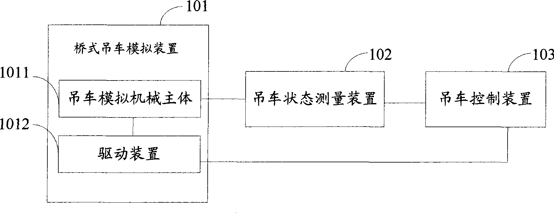
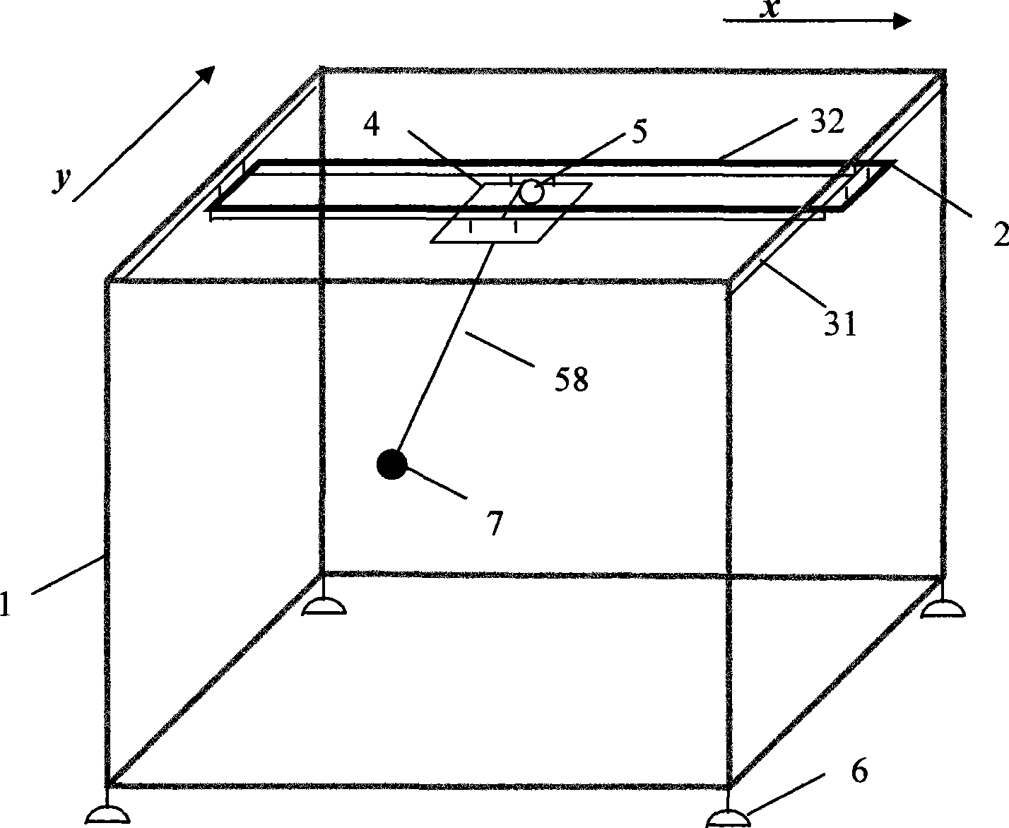
The invention discloses a bridge crane automatic control experimental system which comprises a real bridge crane simulating device, a crane state measuring device and a crane control apparatus, wherein, the bridge crane simulating device is used for simulating a structure of a real bridge crane system which is a control object of the whole experimental system; the crane state measuring device is used for measuring the state quantity information of the bridge crane simulating device in real time and sends the information to the crane control apparatus; and the crane control apparatus is used for receiving the state quantity information of the bridge crane simulating device, which is measured by the crane state measuring device, calculates a corresponding control signal at real time by a preset control method according to the state quantity information and then sends the control signal to the bridge crane simulating device, so as to control the bridge crane simulating device to operate according to preset requirement. The bridge crane automatic control experimental system reflects the kinematic and dynamic characteristics of the bridge crane actually and can validate the practical effect of existing different crane control methods.

Description

technical field [0001] The invention relates to the technical field of automatic control of nonlinear underactuated systems, in particular to an automatic control experiment system for bridge cranes. Background technique [0002] As we all know, an overhead crane is a very common assembly transportation tool. It uses ropes to connect the load to the trolley on the crane, and transports the load to the designated location through the movement of the trolley. The overhead crane is used in ports, warehouses, etc. , Construction sites and other places have been widely used. [0003] In view of the fact that when the bridge crane is running, the movement of the trolley on the crane will cause the load to swing, so that the load may collide with the surrounding operators or other objects, resulting in damage to the load and even casualties, especially when the trolley After arriving at the designated position and stopping operation, the load suspended by the crane will have a rel...

Claims


Application Information

Patent Timeline
Patent Type & Authority Applications(China)
IPC IPC(8): G09B25/02
Inventor 方勇纯马博军苑英海王鹏程
Owner NANKAI UNIV
Learn More