
Underground mine natural ventilation equipment

A natural ventilation and underground mine technology, which is applied in mine/tunnel ventilation, mining equipment, earthwork drilling, etc., can solve the problems of high electric fire, reduce miners' working strength, and high equipment maintenance costs, and achieve the improvement of physical health, The effect of reducing maintenance workload and reducing infrastructure investment

Inactive Publication Date: 2009-04-29
耿秀
View PDF0 Cites 10 Cited by
  • Summary
  • Abstract
  • Description
  • Claims
  • Application Information

AI Technical Summary

Problems solved by technology

Due to the large amount of equipment, a large amount of heat, magnetic field and vibration will be generated when the equipment is in operation, which will increase the density in the tunnel and form a thermal barrier, so that the air outside the tunnel cannot enter the tunnel smoothly, forming a small circulation in the tunnel, and harmful air in the tunnel. Gas and dust cannot be discharged out of the cave, which not only endangers the health of workers, but also poses safety hazards;
[0004] 2. Due to the large amount of equipment, large infrastructure investment, high energy consumption, high noise, and high equipment maintenance costs increase the production cost of the mine;
[0005] 3. Due to the large number of electrical contacts of the ventilation equipment, the probability of causing an electric fire is also very high, and there are a lot of potential safety hazards;
[0006] 4. Since most of the ventilation equipment is a relay-type ventilation system, as long as one piece of equipment fails, the entire ventilation system will be paralyzed, and the entire roadway will have to stop production;
[0007] 5. Since the harmful gas and dust in the roadway cannot be discharged, it will endanger the health of the workers, reduce the physical strength of the miners, and reduce the production efficiency of the mine

Method used


Image

  • Underground mine natural ventilation equipment

Examples


Embodiment

[0036] A jade mine originally used mechanical forced ventilation equipment. Because the ventilation effect is not good enough, it affects the health of the staff and the economic benefits of the mining enterprise. After adopting the natural ventilation equipment for underground mines of the present invention, the problem of air quality near the tunnel surface in the tunnel is completely solved, and the air quality in the tunnel is close to the air quality outside the mine. Until the air is fresher than before, except for the presence of dust near the face of the blasting operation, the air at other times is clean. The dust generated by the blasting operation can be sucked away by the ventilation equipment in a very short time, thus avoiding the harm to the health of workers and various safety hazards caused by poor ventilation.


PUM


Abstract

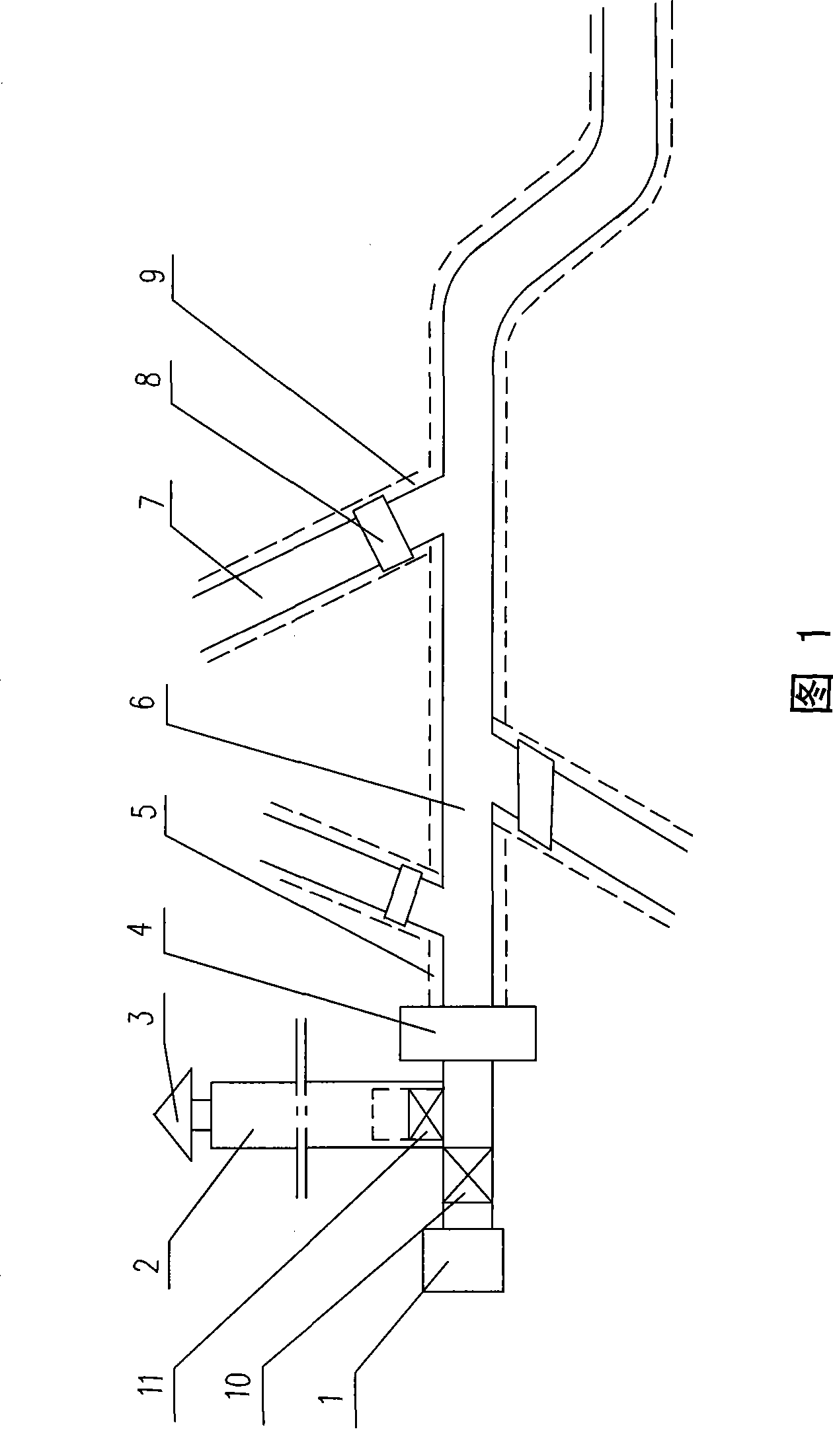
The invention relates to the technical field of underground mine ventilation equipment, especially an underground mine natural ventilation equipment which comprises a large vertical chimney arranged near the pit opening, a main ventilating duct arranged in the main tunnel of the underground mine, and a bottom surface having an outlet higher than the large vertical chimney, wherein the top of the large vertical chimney is provided with an umbrella shape cover, and the diameter of the large vertical chimney is two to four times of that of the main ventilating duct. When the main tunnel of the underground mine is connected with the branch tunnel, the main ventilating duct is provided a with corresponding branch ventilating duct, the connection place is provided with a hermetically sealed butterfly valve, and the distance from the inlet of the ventilating duct to the tunnel face is one to four meters. The bottom of the large vertical chimney is connected with a draft fan, and another side is provided with an ash removal opening which can be closed. The ventilating duct is an abrasion resistant and corrosion resisting elastic hermetically sealed duct and is arranged on the top of the tunnel. The inlet of the ventilating duct is an expansion opening. The invention thoroughly solves the air quality problem adjacent to the tunnel face in the tunnel, and thereby avoids the harm to the workers' health and various safety hidden troubles caused by the bad ventilation.

Description

technical field [0001] The invention relates to the technical field of ventilation equipment for underground mines, in particular to natural ventilation equipment for underground mines. Background technique [0002] Existing underground mine underground ventilation equipment all adopts mechanical forced ventilation equipment. The disadvantages of this type of mechanical forced ventilation are numerous: [0003] 1. It cannot fundamentally solve the harmful gas and dust hazards in the roadway. The reason is that there are many ventilation devices, many contacts, and many leakages. Due to the large amount of equipment, a large amount of heat, magnetic field and vibration will be generated when the equipment is in operation, which will increase the density in the tunnel and form a thermal barrier, so that the air outside the tunnel cannot enter the tunnel smoothly, forming a small circulation in the tunnel, and harmful air in the tunnel. Gas and dust cannot be discharged out ...

Claims


Application Information

Patent Timeline
IPC IPC(8): E21F1/18
Inventor 耿秀耿霞
Owner 耿秀
Learn More