
Binding machine with mark post

A stapler and benchmarking technology, applied in binding and other directions, can solve problems such as unsatisfactory use effect

Inactive Publication Date: 2009-04-29
陈烁
View PDF0 Cites 4 Cited by
  • Summary
  • Abstract
  • Description
  • Claims
  • Application Information

AI Technical Summary

Problems solved by technology

[0002] The stapler is a commonly used tool in the process of learning and office work. Because there is no marking device specially used to mark whether the book to be bound is placed correctly or not, the common such equipment often makes the stapled nails crooked. Some staplers have also noticed this problem. There is a horizontal line engraved near the nail seat at the front end of the base, but the effect is not very satisfactory.

Method used


Image

  • Binding machine with mark post
  • Binding machine with mark post

Examples


Embodiment Construction

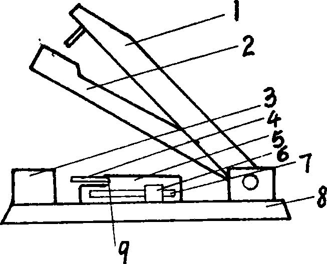
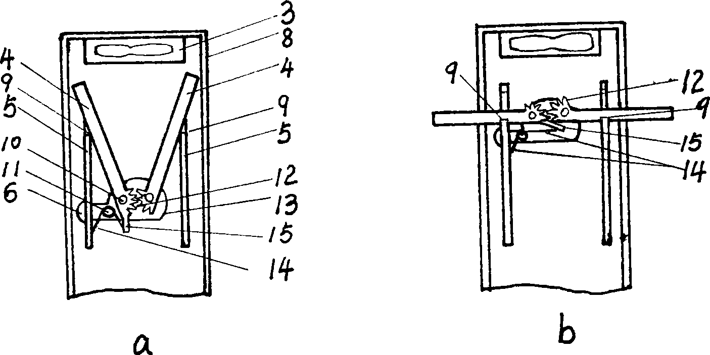
[0009] like figure 1 , the general structural form of the stapler is made up of base 8, nail box 2, pressing arm 1, and the key part of this design is installed on the middle section of the machine base, and its part is fixed by a plate through folding into a groove shape. The left and right side parts are the left and right side walls 5 respectively, and the left side wall has a longitudinal long mouth and is a chute 7, and the front part of the upper side of the left and right side walls is processed with the same gap to become a stop 9, and the slide block 6 is front-viewed. Square, when looking down, the outer side becomes arc-shaped, close to the outside of the left side wall, and a horizontal sheet-shaped bottom plate 13 is vertically connected with a chute 7 on it, as figure 2 As shown in , the bottom plate 13 is located in the groove between the left and right side walls, the front side is semicircular, and there are two screws 10 arranged side by side on it, and the ...


PUM


Abstract

The invention discloses a stapler provided with a marker post, which consists of a bed, a stapling box, a pressure arm, a side wall, a slide block, a bottom plate, the marker post, a pinning spring, etc. Due to the newly arranged marker post with length rather more than that of the stapler body, the stapler offers a clear and palpable reference mark for the right arrangement of a binding piece, therefore, the binding quality is ensured and the stapler can be folded after use.

Description

technical field [0001] The invention relates to the field of stationery and office work, in particular to a binding machine. Background technique [0002] The stapler is a commonly used tool in the process of learning and office work. Because there is no marking device specially used to mark whether the book to be bound is placed correctly or not, the common such equipment often makes the stapled nails crooked. Some staplers have also noticed this problem. There is a horizontal line engraved near the nail seat at the front end of the base, but the effect is not very satisfactory. Contents of the invention [0003] The purpose of the present invention is exactly to provide a kind of new technical scheme of stapler, and it can eliminate above-mentioned defective. [0004] This technical solution is achieved in this way: the left and right side walls are installed on the left and right sides of the base of the stapler, which can be folded into a groove shape with a thin plat...

Claims


Application Information

Patent Timeline
Patent Type & Authority Applications(China)
IPC IPC(8): B42B4/00
Inventor 陈烁
Owner 陈烁
Learn More