
Field apparatus

A technology of field equipment and equipment functions, applied in the direction of instruments, computer control, simulators, etc., can solve the problem that the functions are not huge, and achieve the effect of simplifying inventory

Active Publication Date: 2009-04-22
SIEMENS AG
View PDF0 Cites 9 Cited by
  • Summary
  • Abstract
  • Description
  • Claims
  • Application Information

AI Technical Summary

Problems solved by technology

From the point of view of the field device manufacturer, there are more and more problems in providing suitable devices for each customer's expectations: Naturally, all the functions expected by the respective customers must be provided by the device; but at the same time, the cost aspect must be taken into account and price structure, so that the device is not huge with respect to its functions and can perform more functions than the customer needs and is affordable

Method used


Image

  • Field apparatus
  • Field apparatus
  • Field apparatus

Examples


Embodiment Construction

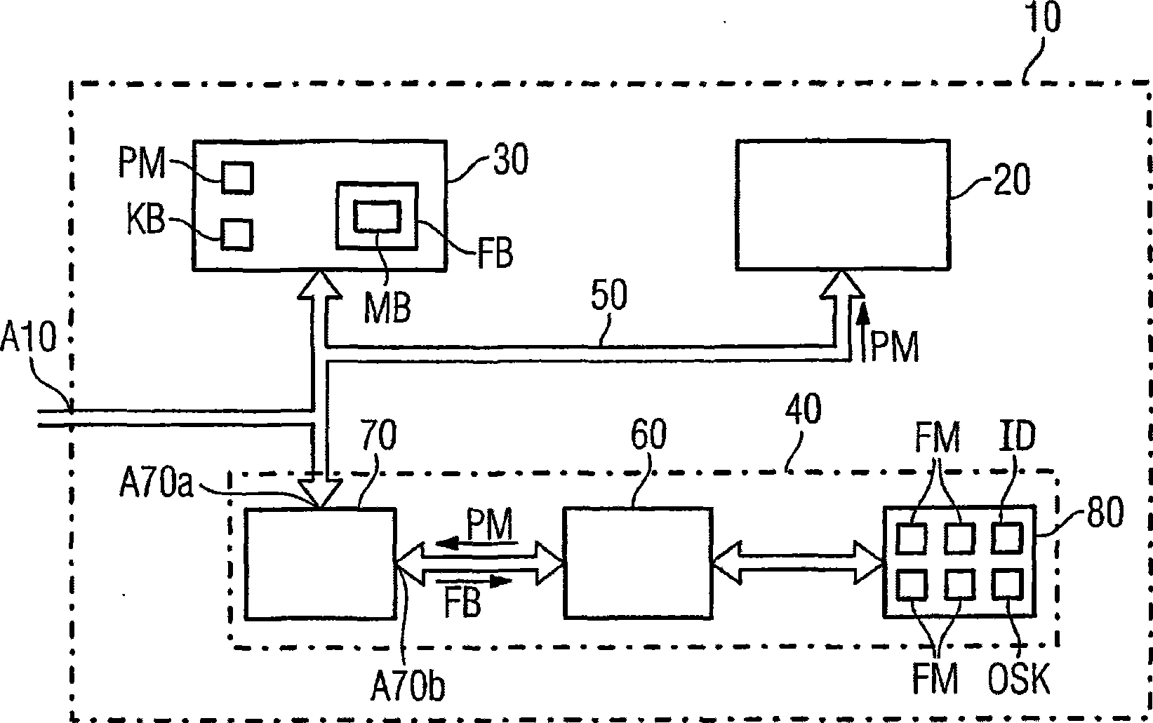
[0027] exist figure 1 A field device 10 can be seen, which is designed with a microprocessor unit 20 as well as a main memory 30 and a safety device 40 . Microprocessor unit 20 , main memory 30 and safety device 40 are connected to one another via a device-internal data bus 50 and to external connection A10 of field device 10 .

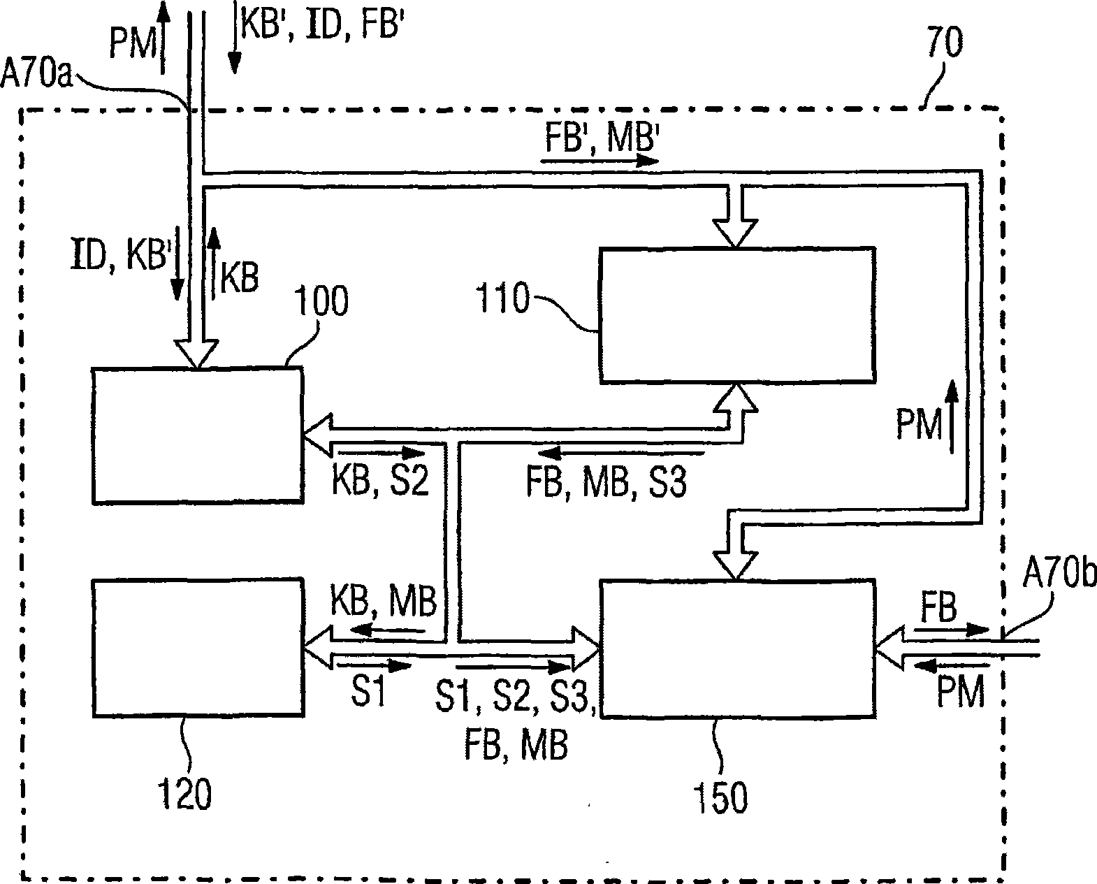
[0028] as in figure 1 As known from , the safety device is designed with an interpreter module 60 , a safety module 70 and a memory area 80 in which the function module FM is stored. The security module 70 is connected to the data bus 50 via a connection A70a and to the interpretation module 60 via a connection A70b.

[0029] according to figure 1 The field device 10 is for example described as follows:

[0030] In a first step which also takes place during manufacture or parameterization of the field device 10 , the marker block KB is stored in the main memory 30 of the field device 10 ; The permissible range of functions for the operation of th...


PUM


Abstract

The invention relates to a field device (10), in particular a protective device, having a microprocessor arrangement (20) which executes a program module (PM), which defines the device function, during operation of the field device. The invention provides for the field device to have a protection device (40) which is configured in such a manner that it checks whether a function description block (FB), which has been input and describes a desired device function, describes an enabled device function and, in the case of a device function which has not been enabled, blocks execution of said function and, in the case of a device function which has been enabled, enables execution of said function.

Description

technical field [0001] The invention relates to a field device, in particular for use in energy technology devices such as power supply devices, having the features of the preamble of claim 1 . Background technique [0002] Such field devices are formed, for example, by protective devices SIPROTEC 7SA511 and 7SA513 from the company SIEMENS. The protective device is designed with a microprocessor device, which executes program modules that determine device functions during operation of the field device. [0003] Field devices in energy technology systems today perform many functions in protection and control technology. The performance and functionality of devices continues to improve. From the point of view of the field device manufacturer, there are more and more problems in providing suitable devices for each customer's expectations: Naturally, all the functions expected by the respective customers must be provided by the device; but at the same time, the cost aspect mus...

Claims


Application Information

Patent Timeline
Patent Type & Authority Applications(China)
IPC IPC(8): G05B19/042
CPCG05B2219/25125G05B2219/24167G05B19/0428G05B2219/25428G05B2219/33331
Inventor 安德烈亚斯·朱里希斯蒂芬·沃尔兹
Owner SIEMENS AG
Learn More