
Optical lens component

A technology of optical lenses and components, applied in optical components, optics, instruments, etc., to achieve the effect of improving imaging quality, improving imaging quality, and reducing processing costs

Active Publication Date: 2010-12-08
BYD SEMICON CO LTD
View PDF5 Cites 0 Cited by
  • Summary
  • Abstract
  • Description
  • Claims
  • Application Information

AI Technical Summary

Problems solved by technology

This brings great challenges to the design of optical lens components

Method used


Image

  • Optical lens component
  • Optical lens component
  • Optical lens component

Examples


Embodiment Construction

[0031] The present invention will be further described in detail below through specific embodiments and in conjunction with the accompanying drawings.

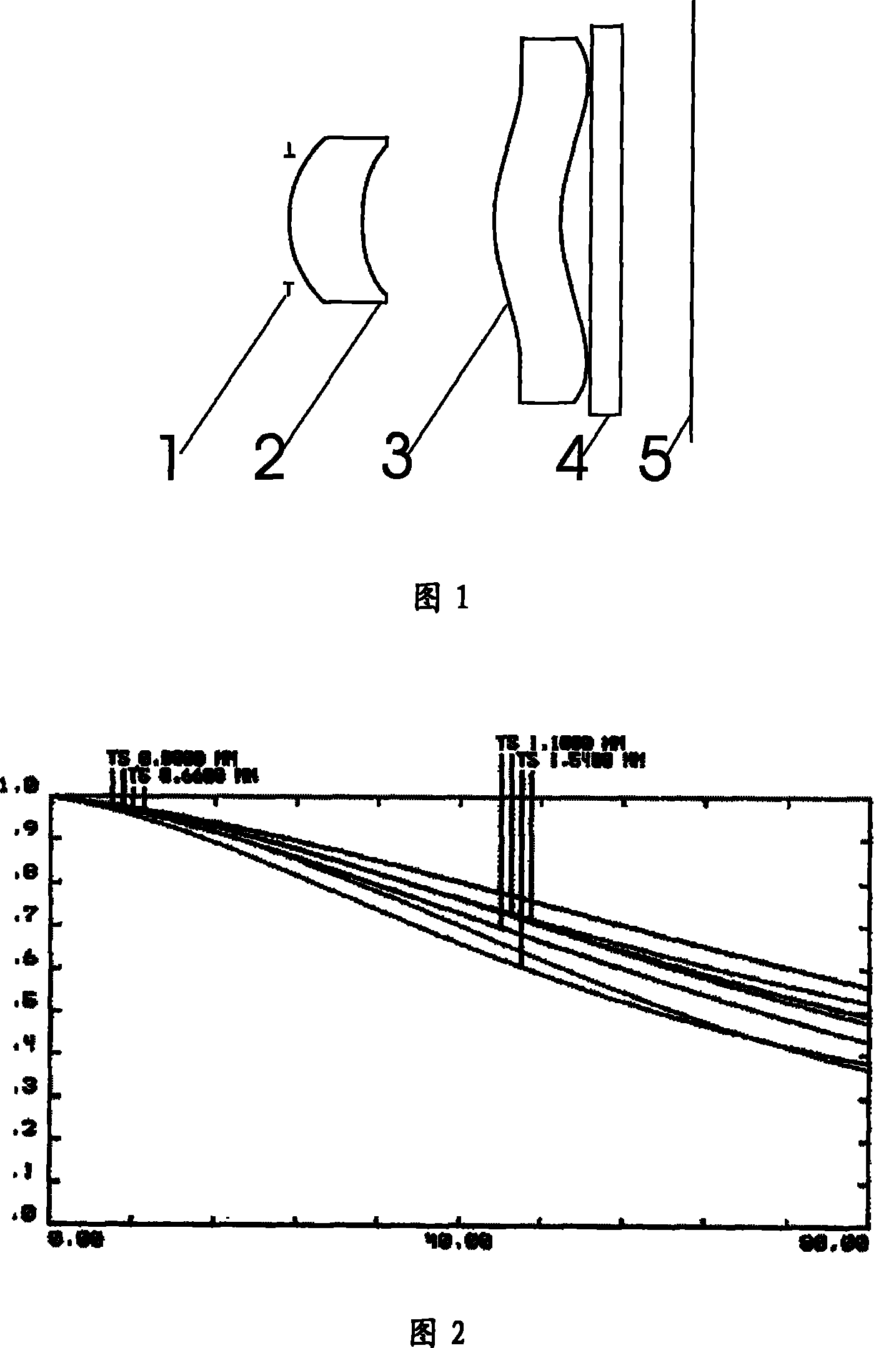
[0032] Such as Figures 1 to 12 As shown, an optical lens assembly includes a lens group, which is composed of a first lens 2 with a positive diopter and a second lens 3 with a negative diopter that have a common optical axis and are arranged in sequence from the object direction image side, Wherein the first lens 2 has a first surface facing the object side and a second surface facing the image side, the first surface protrudes toward the object side, and the second surface is concave relative to the image side; the second The lens 3 has a third surface facing the object side and a fourth surface facing the image side. The third surface is wavy with the middle part protruding toward the object side, and the two sides are concave relative to the object side. The four surfaces are wavy in which the middle part is concave relat...


PUM

PropertyMeasurementUnit
lengthaaaaaaaaaa
thicknessaaaaaaaaaa

Abstract

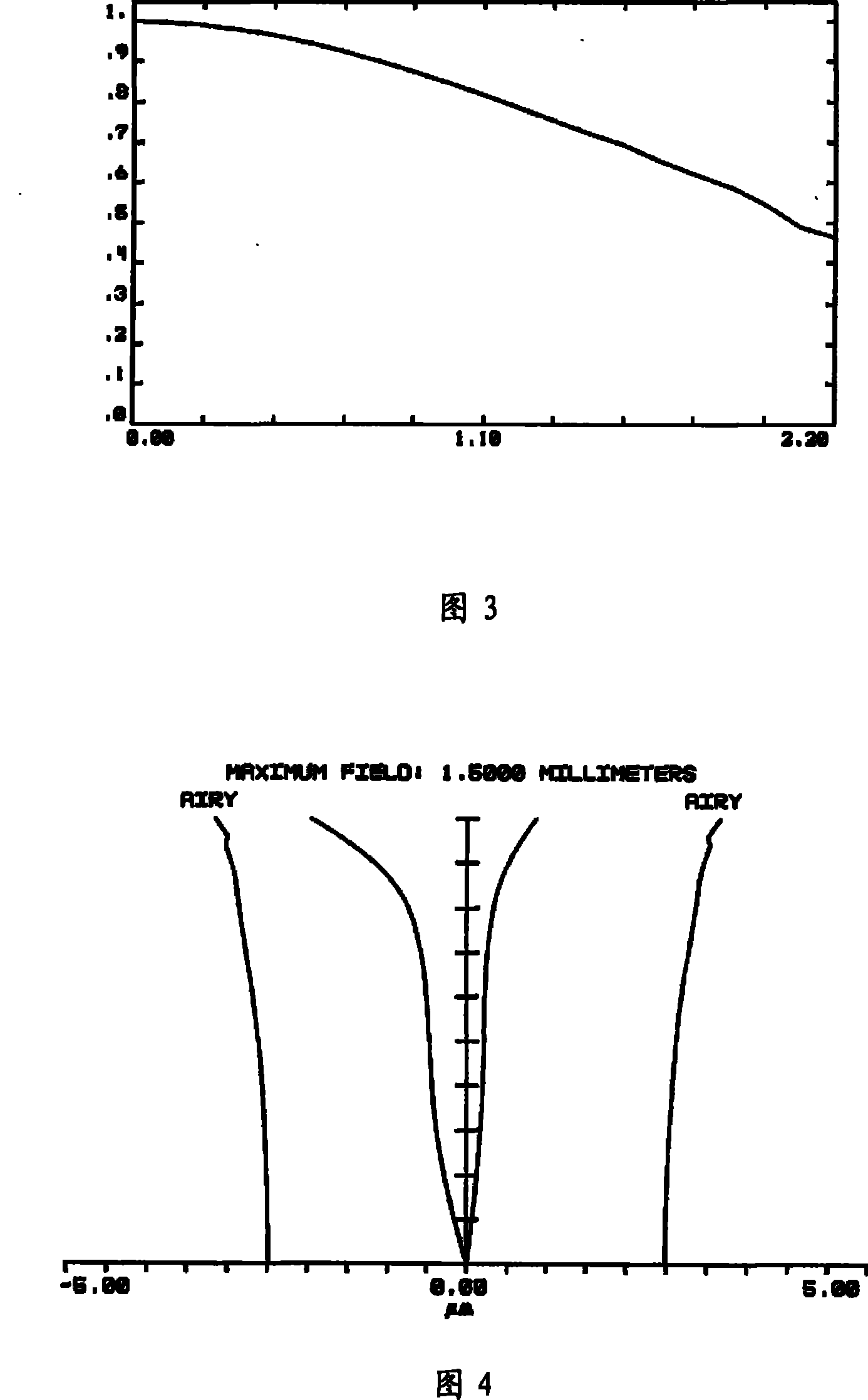
The invention discloses an optical lens component which is suitable for mobile phones and minitype digital camera; the component comprises a combination of lenses consisting of a first lens having positive diopter and a second lens having negative diopter which have the same optical axis and are sequentially arranged from the object direction, wherein, the first lens is provided with a first surface facing the object direction and a second surface facing the image direction; the first surface projects towards the side of the object direction, and the second surface is concave correspondingly to the side of image direction; the second lens is provided with a third surface facing the object direction and a fourth surface facing the image direction; the third surface is a wave shape, and hasthe middle part being convex towards the side of the object direction and the two sides being concave corresponding to the side of the object direction; the fourth surface is a wave shape, and has the middle part being concave corresponding to the side of the image direction and the two sides being convex towards the side of the image direction; the first, the second, the third and the fourth surfaces are non-spherical surface. The optical lens component provided by the invention has less number of lenses and compact structure, and can effectively reduce various optical aberrations such as spherical aberration, meridianal coma, astigmatism, field curvature, etc.

Description

technical field [0001] The invention relates to optical devices, in particular to an optical lens assembly. Background technique [0002] Optical imaging lens is an important component of digital imaging equipment. In recent years, VGA cameras have become standard configurations in low-end and mid-range mobile phones. How to reduce the production cost as much as possible while ensuring the image quality of the lens has become a hot spot in optical lens design. At the same time, mobile phones are becoming thinner and lighter, which also forces the lens design to require a shorter TTL (Total Lens Optical Length). This brings great challenges to the design of optical lens components. Contents of the invention [0003] A technical problem to be solved by the present invention is to overcome the shortcomings of the above-mentioned prior art and propose a light, thin and short optical lens. [0004] Its technical problem is solved by the following technical solutions: an optic...

Claims


Application Information

Patent Timeline
Patent Type & Authority Patents(China)
IPC IPC(8): G02B9/34G02B13/00G02B13/18G02B1/02G02B1/04
Inventor 姜莉莉
Owner BYD SEMICON CO LTD
Learn More