
Centrifugal fan

A centrifugal fan and fan frame technology, which is applied to components of pumping devices for elastic fluids, non-variable pumps, pump devices, etc., can solve the problems of fan noise increase and discomfort, and reduce disturbance and noise Effect

Inactive Publication Date: 2009-04-22
FU ZHUN PRECISION IND SHENZHEN +1
View PDF0 Cites 6 Cited by
  • Summary
  • Abstract
  • Description
  • Claims
  • Application Information

AI Technical Summary

Problems solved by technology

However, when the fan speed increases, the noise generated by the fan will increase significantly, and the users who are located near the centrifugal fan will feel uncomfortable or even unbearable.

Method used


Image

  • Centrifugal fan
  • Centrifugal fan
  • Centrifugal fan

Examples


Embodiment Construction

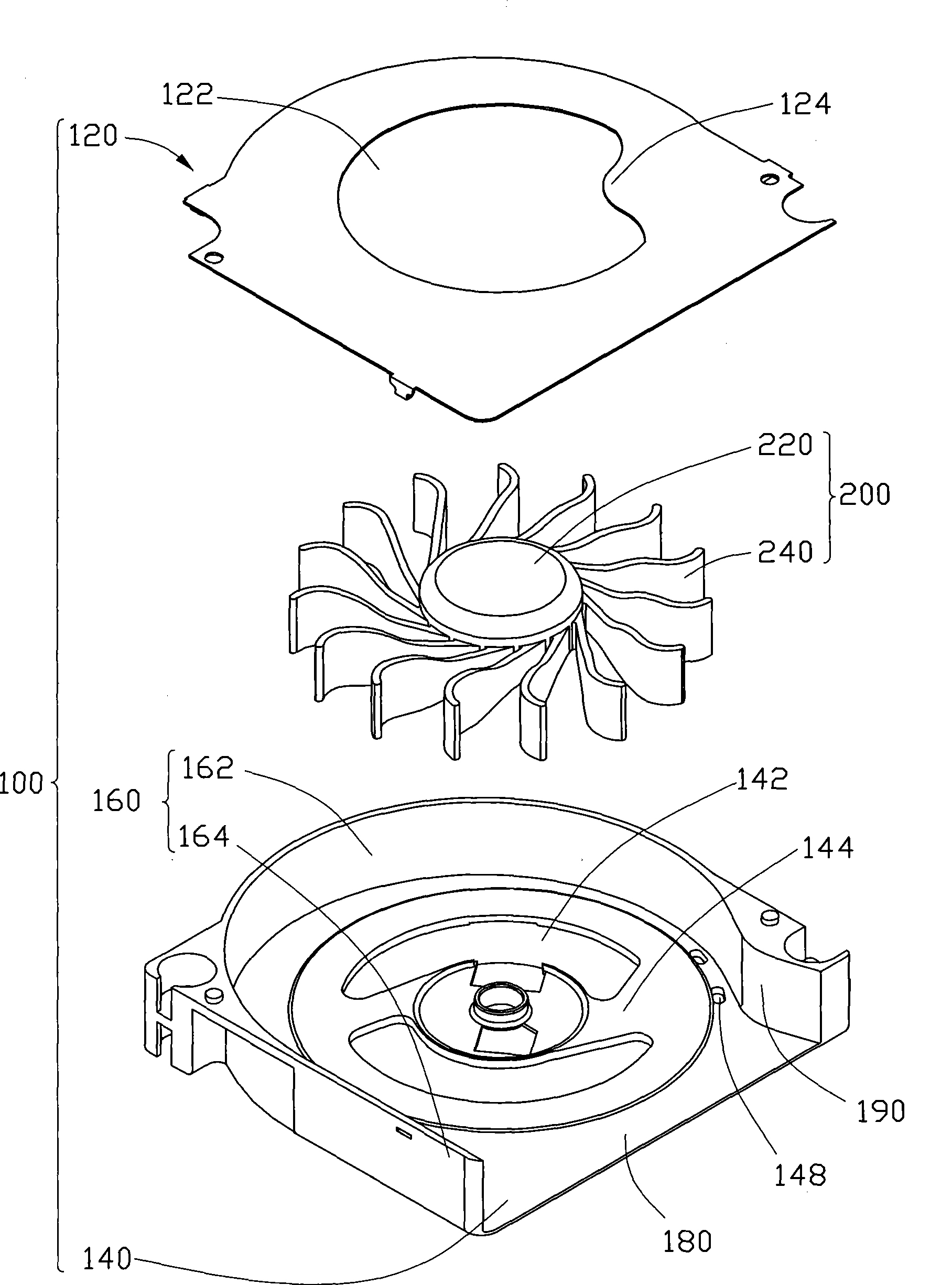
[0011] see figure 1 and figure 2 , are three-dimensional assembly and exploded views of a centrifugal fan according to a preferred embodiment of the present invention. The centrifugal fan can be combined with a heat dissipation device (not shown) to dissipate heat from heat-generating electronic components.

[0012] The centrifugal fan includes a fan frame 100 and an impeller 200 accommodated in the fan frame 100 . The impeller 200 includes a hub 220 and a plurality of blades 240 radially extending from the periphery of the hub 220 , the blades 240 are inclined clockwise, and the ends of the blades 240 are curved counterclockwise.

[0013] The fan frame 100 includes a cover plate 120 , a bottom plate 140 and a side wall 160 disposed between the cover plate 120 and the bottom plate 140 . Wherein, the side wall 160 is a semi-closed structure extending upward from the periphery of the bottom plate 140 , and includes an arc-shaped surface 162 and a straight surface 164 . An a...


PUM


Abstract

The invention discloses a centrifugal fan. The fan comprises a fan frame and an impeller received in the fan frame, wherein the fan frame is provided with a first air inlet, an air outlet and a tongue part close to the air outlet as well as a protrusion which is positioned in the air inlet and close to the tongue part. The centrifugal fan comprises a fan frame and an impeller received in the fan frame, wherein the fan frame comprises a cover plate, a bottom plate and a side wall arranged between the cover plate and the bottom plate, the impeller is arranged in a space enclosed by the cover plate, the bottom plate and the side wall, the side wall is provided with an air outlet and a tongue part close to the air outlet, the cover plate is provided with a first air inlet and a protrusion positioned in the first air inlet, and the bottom plate is provided with a vent close to the tongue part. The protrusion is arranged in the first air inlet to reduce air intake in the first air inlet, so the influence of redundant air on the tongue part is reduced and noises are further reduced.

Description

technical field [0001] The invention relates to a centrifugal fan, in particular to a centrifugal fan with relatively low noise. Background technique [0002] At present, with the rapid development of the computer industry, more and more heat is generated by heat-generating electronic components such as chips in notebook computers. In order to dissipate these excess heat effectively, the existing method is to attach a heat sink on the surface of the heating electronic component, and then arrange a centrifugal fan on the heat sink, and utilize the cooling airflow generated by the centrifugal fan to cool the heat sink. Forced heat dissipation, thereby dissipating the heat generated by heat-generating electronic components. Because the size of the airflow generated by the fan depends on the rotation speed of the fan, in order to further improve the performance of the fan, the rotation speed of the fan must be increased. However, when the fan speed is increased, the noise gene...

Claims


Application Information

Patent Timeline
Patent Type & Authority Applications(China)
IPC IPC(8): F04D29/42
CPCF04D29/4213F04D25/0613
Inventor 黄清白赵志辉张文杰
Owner FU ZHUN PRECISION IND SHENZHEN
Learn More