Power generation control device

一种发电控制、发电机的技术,应用在电路装置、发电机控制零部件、电池电路装置等方向,能够解决无法大幅地改善引擎平滑性、引擎旋转缺乏平滑性、很难减轻转矩变动等问题,达到旋转稳定、抑制负荷的增大、吸气效率稳定的效果

Inactive Publication Date: 2009-04-01
HONDA MOTOR CO LTD
View PDF2 Cites 4 Cited by
  • Summary
  • Abstract
  • Description
  • Claims
  • Application Information

AI Technical Summary

Problems solved by technology

On the other hand, in a four-cycle engine, the frictional force (the force acting in the opposite direction to the direction in which the piston moves in terms of the engine's function when the engine is operating) differs depending on each cycle (stroke), so even if the frictional force is not considered , it is difficult to reduce the torque variation caused by the frictional force difference between strokes only by controlling the power generation amount applied to the overall load state of the engine
[0008] In particular, when the engine is running in a low-speed region, the overall output torque is small, so even if the amount of power generation is limited, there will be torque fluctuations caused by differences in friction between strokes, which will cause engine damage. Cases where rotation lacks smoothness
That is, there are cases where the smoothness of engine rotation cannot be greatly improved even if the power generation amount is controlled only depending on the general load state.

Method used


Image

  • Power generation control device
  • Power generation control device
  • Power generation control device

Examples


Embodiment Construction

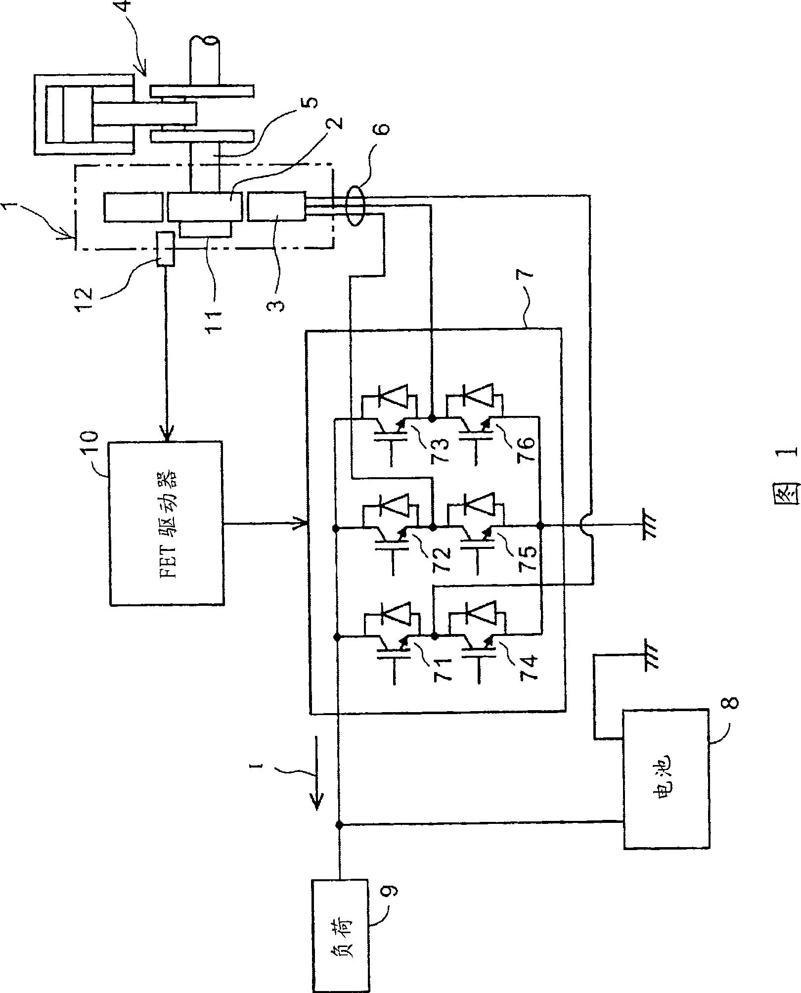
[0026] Hereinafter, an embodiment of the present invention will be described with reference to the drawings. FIG. 1 is a diagram showing a system configuration of a charge control device according to an embodiment of the power generation control device of the present invention.

[0027] In FIG. 1 , a generator 1 is composed of an internal gear 2 and an external stator 3 , and the internal gear 2 is connected to one end of a crankshaft 5 of a four-cycle engine 4 . The outer stator 3 has a three-phase output coil 6 connected to an input side of a switching circuit 7 . The output side of the switch circuit 7 is connected to the battery 8 and the load 9 . The switch circuit 7 is a three-phase bridge circuit composed of six FETs 71 , 72 , 73 , 74 , 75 , and 76 . The FET driver 10 is provided as an output control device that changes the energization phases of the FETs 71 to 76 of the switch circuit 7 to perform duty control.

[0028] The internal gear 2 of the generator 1 is prov...


PUM


Abstract

A generating controller of this invention performs minimum power generation via reducing engine torque fluctuations caused by load of power generation. A crank rotating angle using engine speed (Ne) and an upper stopping point as standard are detected based on pitch singles input from a crank rotating angle sensor (12). Functions of the engine speed (Ne) corresponding to the route having minimal friction force in whole circulation is used for pre-storing charge periods with different lengths. A charge period determining unit (18) compares the crank rotating angle and the charge period and inputs a charge control signal into an AND gate (104) when the present crank rotating angle is judged as the predetermined charge period. A duty determined by a regulated voltage control block (102) is set in a duty ratio setting unit (103) and is input to a switch circuit (7) when the AND gate (104) is opened.

Description

technical field [0001] The present invention relates to a power generation control device, and more particularly to a power generation control device that controls to supply an output current of an engine generator to a battery or a load only in a predetermined region where the frictional force of the engine is small. Background technique [0002] An engine-driven vehicle such as a motorcycle or a four-wheeled vehicle has a generator driven by the engine, and a battery for supplying electric power used in the vehicle is charged by an output current of the generator. In addition, generally, an on-vehicle generator is also used as an engine starting motor. [0003] It is known that the amount of power generated by an on-vehicle generator is variably controlled according to the load on the engine. For example, in the (Japanese) Special Publication No. 3-504407, a battery charging method is proposed. In the alternator-type battery charging method that stops the power generation...

Claims


Application Information

Patent Timeline
Patent Type & Authority Applications(China)
IPC IPC(8): H02J7/14H02P9/00
CPCH02P9/02H02P9/08
Inventor 齐藤贤二郎柴田和己
Owner HONDA MOTOR CO LTD
Why Eureka
Try Eureka