
Water-shutoff method for sealing gas well effluent section by combination of incline cement and gas injection compression

A gas injection and section technology, which is applied in earth-moving drilling, sealing/isolation, wellbore/well components, etc., and can solve problems such as curing problems, inability to fill pores, and inability to plug

Inactive Publication Date: 2009-04-01
CPC CORPORATION
View PDF0 Cites 6 Cited by
  • Summary
  • Abstract
  • Description
  • Claims
  • Application Information

AI Technical Summary

Problems solved by technology

[0009] However, this construction method has several disadvantages. First, it must overcome the dilution effect of cement milk (or resin) mixed with formation water, otherwise there will be problems in subsequent curing Furthermore, it is necessary to ensure that the gravel layer is not subject to excessive fouling and uneven conductivity. The role of the gravel layer is to prevent sand. After production, the gravel layer will inevitably be fouled by silt from the production layer. Milk or resin, even if it can flow into the gravel layer by gravity alone, may not be able to fill all the pores and therefore not completely seal off the bottom water cone
In addition, after water comes out of the production well, there is usually water column accumulation at the bottom of the well. When the cement milk or resin is placed at the bottom of the well, the formation water will form a film on the well wall. When the cement milk or resin is cured and the well is restarted , There is often a differential pressure of tens to hundreds of pounds between the bottom of the well and the formation. This differential pressure will cause the bottom water to flow into the well along the tiny gap between the cement emulsion and the well wall, and cannot completely seal the water layer. As mentioned above , water plugging with thermosetting resin, when the differential pressure at the bottom of the well exceeds 50 pounds, the formation water will penetrate the joint between the gravel layer and the well wall

Method used


Image

  • Water-shutoff method for sealing gas well effluent section by combination of incline cement and gas injection compression
  • Water-shutoff method for sealing gas well effluent section by combination of incline cement and gas injection compression
  • Water-shutoff method for sealing gas well effluent section by combination of incline cement and gas injection compression

Examples


Embodiment Construction

[0038] In order to further have a deeper, clear and detailed understanding and understanding of the structure, use and characteristics of the present invention, a preferred embodiment is now given, and the details are as follows in conjunction with the drawings:

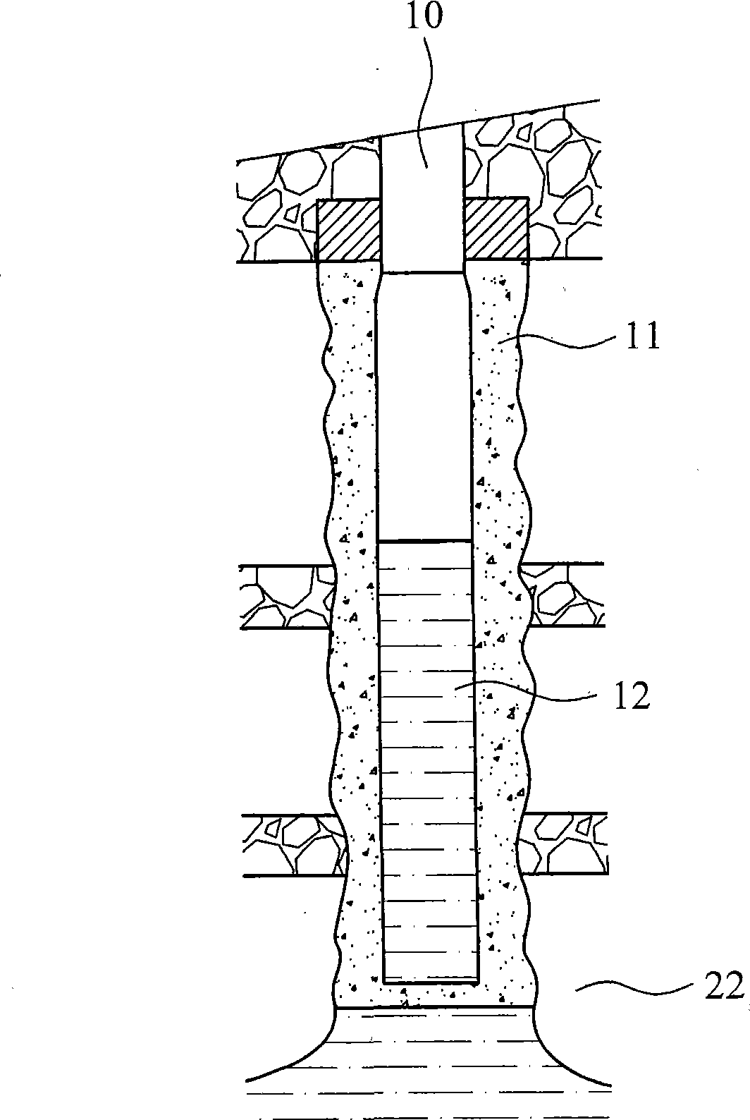
[0039] See first figure 1 , after the production of the gravel-packed production well 10, due to the rise of the gas-water interface, the accompanying water is also sucked out while the gas is produced. From the illustrated embodiment, the above-mentioned gravel-packed production well 10 drills through three layers of oil and gas layers, from top to bottom The bottom is the first oil and gas production layer 20, the second oil and gas production layer 21 and the third oil and gas production layer 22, and the impermeable layers between the above production layers are shale layers. In the third oil and gas production layer 22, it is clearly seen that the water cone rises into the gravel-filled production well 10, so th...


PUM


Abstract

The invention relates to a water shutoff method for closing a water-yielding region of a gas well by utilizing dumping cement for matching with gas injection and compression. Gas injection is carried out to a target well so as to shove stored water in the well to the stratum and cause the well to maintain no water; meanwhile, a dump bailer is dropped down by a cabled twist and caused to be vertical to the section to be closed in the stratum; when reaching the closed section, the opening of the bottom of the dump bailer is opened to lead laitance arranged inside to flow out; the laitance flows out and first accumulates in the closed section and then slowly flows to a sieve tube and the gravel stratum in annular rings among the well wall, and gas injection is continued until the laitance solidifies and hardens so as to fulfill the purpose of blocking up the water-yielding stratum.

Description

technical field [0001] The invention relates to a water plugging method for closing the water outlet section of a gas well by using tilting cement combined with gas injection and pressurization, in particular, it refers to the treatment of the water outlet situation of the gravel-filled gas well water cone, and pushes the accumulated water by means of gas injection and pressurization Return to the formation, and squeeze the cement milk to the gap between the gravel and the well wall, and the cement milk will solidify and seal, so that the section will form a reliable closed section. Background technique [0002] During the production of gas wells, there are natural gas and water in the strata that are exploited. The specific gravity of natural gas is lower than that of water, so the natural gas will be stored on the water surface. During the production of natural gas, the pressure of the gas storage layer will gradually drop, and the The water will gradually rise close to th...

Claims


Application Information

Patent Timeline
IPC IPC(8): E21B33/138
Inventor 孙启三吴健一吴佳水范来富黄德坤范振晖
Owner CPC CORPORATION
Learn More