Transitional rolling bed with electric elevating apparatus for front axle end head

A lifting device and transition roller technology, which is applied in the direction of transportation and packaging, conveyor objects, roller tables, etc., can solve the problems of difficult manufacturing, large structure occupation space, and insufficient compactness of movement, etc., to achieve excellent durability and compact overall structure Effect

Inactive Publication Date: 2009-03-25
MIRACLE AUTOMATION ENG CO LTD
View PDF0 Cites 4 Cited by
  • Summary
  • Abstract
  • Description
  • Claims
  • Application Information

AI Technical Summary

Problems solved by technology

[0002] Due to the structure of the factory building, the foundation heights of the two roller bed conveyors are different, and a transition roller bed that can be lifted is needed between the two roller beds. In the past, the lift transition roller bed used a motor to drive the crank rocker to raise the roller bed on the lifting frame. decline, its structure takes up too much space and its movements are not compact enough, and it is difficult to manufacture and other defects

Method used


Image

  • Transitional rolling bed with electric elevating apparatus for front axle end head
  • Transitional rolling bed with electric elevating apparatus for front axle end head
  • Transitional rolling bed with electric elevating apparatus for front axle end head

Examples


Embodiment Construction

[0015] The present invention will be further described below in conjunction with specific drawings and embodiments.

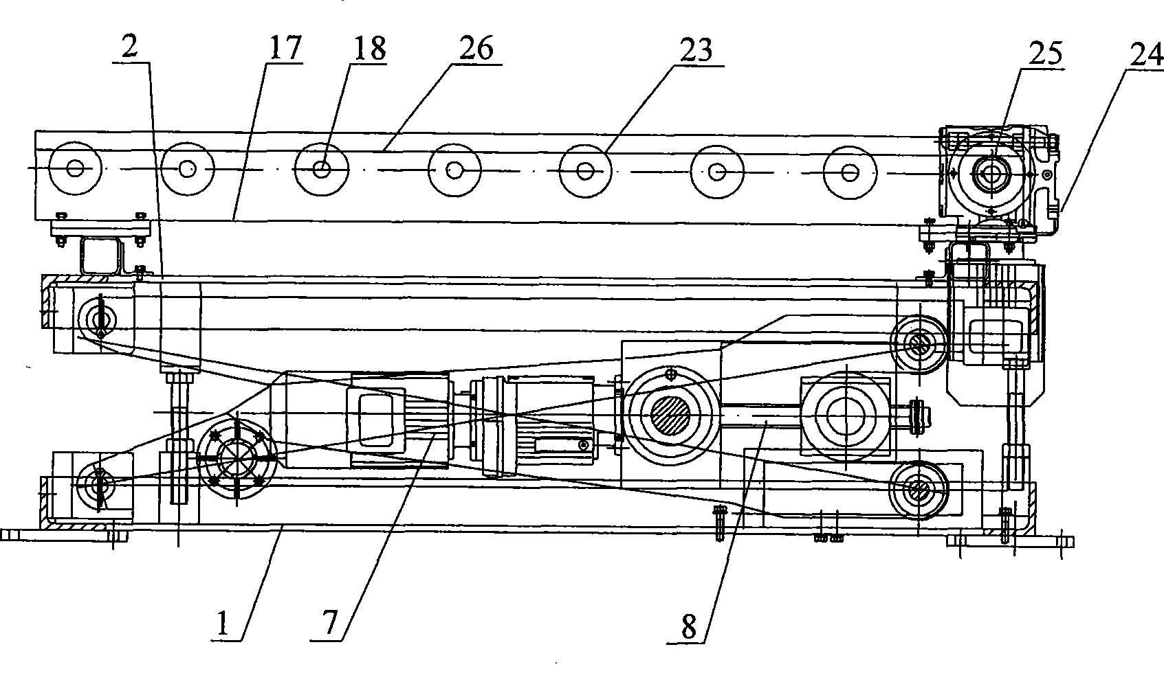
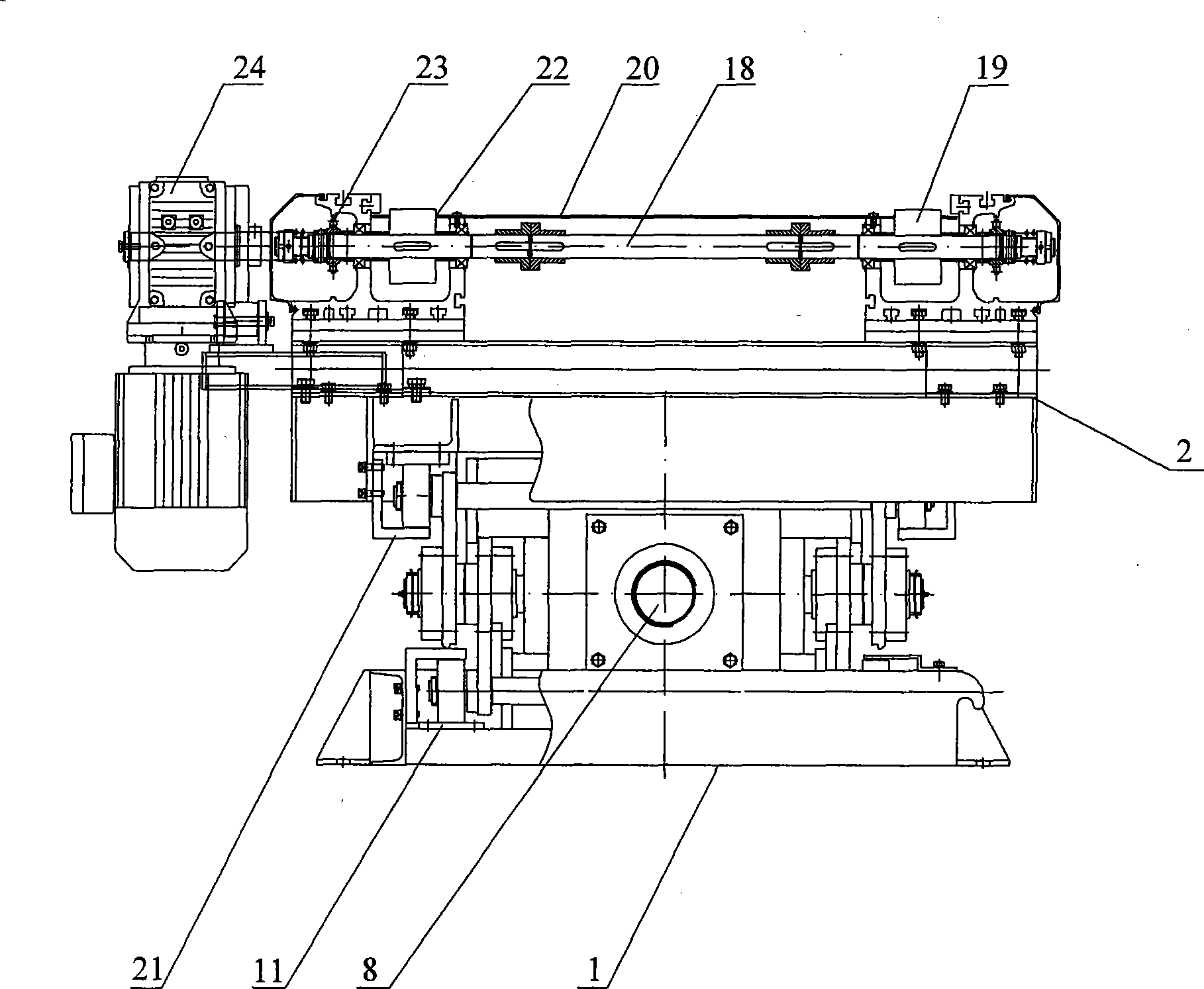
[0016] As shown in the figure: the present invention mainly consists of base plate 1, installation top plate 2, first driving arm 3, second driving arm 4, first roller 5, second roller 6, driving motor 7, screw mandrel 8, screw mandrel nut 9 , mounting seat 10, lower rail 11, first mounting part 12, second mounting part 13, first push rod 14, second push rod 15, main shaft 16, roller bed frame 17, roller shaft 18, roller 19, cover Plate 20, upper slide rail 21, groove body 22, transmission sprocket wheel 23, roller bed motor 24, drive sprocket wheel 25 and transmission chain 26 etc. are formed.

[0017] The present invention includes installing the fixed roller bed base frame 17 on the top plate 2, erecting a number of roller shafts 18 which are arranged parallel to the roller bed frame 17 and connected to it in rotation. There is a cover plate 20, and a groov...


PUM


Abstract

The invention relates to a transition roller machine provided with an electronic elevation device used for a head end of a front axle. The transition roller machine comprises a chassis fixed on a mounting top-plate. A plurality of roller shafts which are arranged in parallel are rotationally connected with the chassis of the roller machine and rollers are fixed at two ends of the roller shafts. A covering plate is arranged above the roller shafts and grooves are arranged on the covering plate where rollers exist so as to lead the wheel faces of rollers to partially rise upwards from the grooves; transmission chain wheels are respectively fixed at two ends of the roller shafts; a roller machine motor is arranged on the chassis of one side and a driving chain wheel is fixed on an output shaft of the roller machine motor; a transmission chain is arranged around the driving chain wheel and the transmission chain wheel; and a bottom plate is arranged under the mounting top-plate and an electronic elevation device used for the mounting top-plate is arranged on the bottom plate. When in working, the transition roller machine can realize the transition of work pieces between two roller machines of different heights with an excellent durability and the elevation of work pieces of different weights, and can largely reduce the shake and noise emerging during the elevation process.

Description

technical field [0001] The invention relates to a lifting device for transporting an empty pallet to a lower return roller table at the end of a front axle conveying line, in particular to a transition roller bed with an electric lifting device for the end of a front axle, and belongs to the technical field of mechanical automation conveying. Background technique [0002] Due to the structure of the factory building, the foundation heights of the two roller bed conveyors are different, and a transition roller bed that can be lifted is needed between the two roller beds. In the past, the lift transition roller bed used a motor to drive the crank rocker to raise the roller bed on the lifting frame. decline, its structure takes up too much space and its actions are not compact enough, and it is difficult to manufacture and other defects. Contents of the invention [0003] The purpose of the present invention is to overcome the deficiencies in the prior art, to provide a workp...

Claims


Application Information

Patent Timeline
IPC IPC(8): B65G47/64B65G13/12
Inventor 魏明利甘玉
Owner MIRACLE AUTOMATION ENG CO LTD
Why Eureka
Try Eureka