


Quick Research
Generate reliable direction feasibility study reports for your R&D in just a few steps.

Technical Q&A
Discover and master advanced knowledge NOW. Basics, ideas, possibilities, all at once.

Find Solutions
As an expert in R&D theories, this can generate solutions to your technical problems instantly.

Evaluate Feasibility
Analyze your overall solution with one click, know your potential R&D risks in advance.

Monitor Landscape
Get weekly tech updates, stay abreast of the latest tech innovations and key insights.
Multi-group steel coil seat frame lifting appliance
A technology of seat frame and steel coil, applied in the direction of load hanging components, transportation and packaging, can solve the problems of time-consuming and laborious safety hazards, and achieve the effects of reliable use, low failure rate, and improved turnover transportation efficiency.
- Summary
- Abstract
- Description
- Claims
- Application Information
AI Technical Summary
Problems solved by technology
Method used
Image

Examples
Embodiment 1
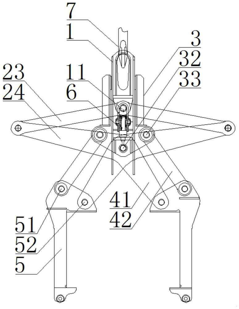
[0027] see figure 1 , a multi-group steel coil seat frame spreader, characterized in that it includes a lifting lug 1, a vertical guiding mechanism, a connecting frame 3, a translation mechanism, and a limit type boom 5, and the bottom of the lifting lug 1 is equipped with a gate 6. The connecting frame 3 is arranged at the bottom of the lifting lug 1 and is connected with the lifting lug 1 through a vertical guide mechanism. The vertical guiding mechanism is used to realize relative sliding of the lifting lug 1 and the connecting frame 3 along the vertical direction. Two groups arranged symmetrically on the vertical center line, and the limit type boom 5 is connected to the connecting frame 3 through a translation mechanism;
[0028] The vertical guide mechanism includes: guide rails 21 fixed on both sides of the lifting lug 1 and arranged in the vertical direction, guide grooves 22 set on the inner side of the top of the connecting frame 3 and nested with the raised guide ra...
Embodiment 2
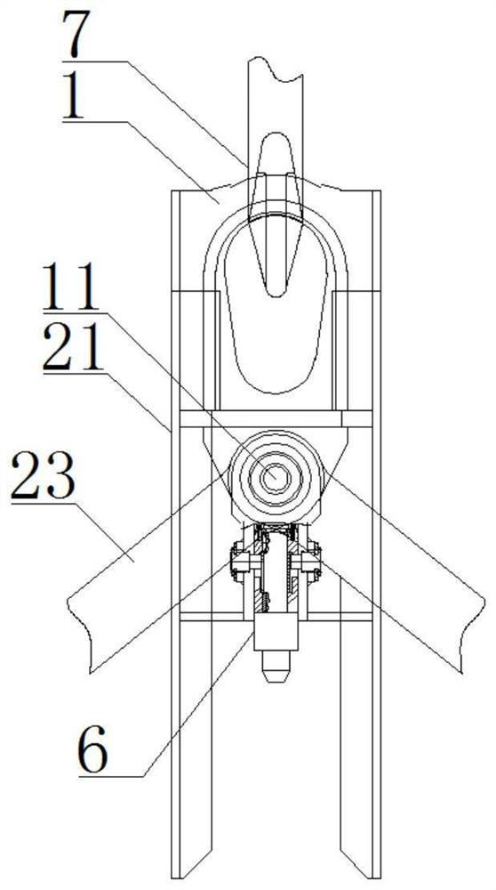
[0031] see Figure 1-2 , 4-6, and combine figure 1 , the vertical guide mechanism, the translation mechanism, and the connecting frame 3 are further described in detail.
[0032] The lifting lug 1 is hung with the general hook 7 of the crane, so that the lifting lug 1 can be used in conjunction with the crane, and the lifting lug 1 and the vertical guide mechanism, connecting frame 3, translation mechanism, and limit position installed on the lifting lug 1 are driven by the crane. The lifting arm 5 moves, and the upper hinge shaft 11 is installed on the lifting lug 1. The upper hinge shaft 11 is installed on the lifting lug 1 by fixed connection or rotating nesting. The upper pull plates 23 on both sides of the vertical center line are at least It includes two groups arranged side by side, and the top ends of the upper pull plates 23 of each group are rotatably mounted on the upper hinge shaft 11 .
[0033] The top of the connecting frame 3 is fixedly connected with a U-shap...
Embodiment 3
[0037] see figure 1 , 6 , and in conjunction with Embodiment 1, the limit type boom 5 in the present invention is further explained and supplemented.
[0038] In order to determine the maximum number of hoisting steel coil mounts and the maximum height limit of the limit-type spreader, the top of the limit-type boom 5 is fixed with a horizontally arranged positioning plane plate 53, so that the steel coil mounts are positioned at the positioning plane. The lower side of the panel 53 is clamped and fixed by two sets of limit-type booms 5, and the bottom of the limit-type boom 5 is rotatably installed with support rollers 54. The mounts are superimposed, and the support roller 54 can be supported on the steel coil mounts that are not hoisted, so that the steel coil mounts above the group of steel coil mounts can be hoisted synchronously through the position-limiting boom 5 .
[0039] The side wall of the position-limiting boom 5 is provided with a box-shaped notch 55, and the ...
PUM
 Abstract
Description
Claims
Application Information
 - R&D Engineer
- R&D Manager
- IP Professional
- Industry Leading Data Capabilities
- Powerful AI technology
- Patent DNA Extraction
Browse by: Latest US Patents, China's latest patents, Technical Efficacy Thesaurus, Application Domain, Technology Topic, Popular Technical Reports.
© 2024 PatSnap. All rights reserved.Legal|Privacy policy|Modern Slavery Act Transparency Statement|Sitemap|About US| Contact US: help@patsnap.com