
A movable fuel-filling station with a device for recovering fuel-gas airtightly

一种加油装置、油气的技术,应用在分配装置、特殊分配装置、液体流量进行控制的装置等方向,能够解决危害身心健康、油气挥发、费用高等问题,达到使用和维护简便、避免污染和损害、防止能源的浪费的效果

Inactive Publication Date: 2009-03-18
SHANGHAI HUAPENG EXPLOSION PROOF TECH
View PDF3 Cites 5 Cited by
  • Summary
  • Abstract
  • Description
  • Claims
  • Application Information

AI Technical Summary

Problems solved by technology

With the acceleration of urbanization, newly built high-rise buildings and residential areas gradually engulf the surrounding environment of gas stations, resulting in the safety distance of these gas stations not complying with the relevant regulations on the design and construction of automobile refueling stations, resulting in gas stations facing Closure, relocation troubles
On the other hand, in order to meet the development needs of the city, new gas stations need to be continuously built, and new stations need to be demolished and land expropriated, facing a series of contradictions due to the lack of urban land. Therefore, reducing the area occupied by gas stations has become a thorny issue
[0003] In addition, oil storage tanks in existing gas stations are rarely equipped with oil gas recovery devices. Even if some oil gas recovery measures are adopted, the effect is mostly unsatisfactory. In the atmosphere, it causes serious pollution to the environment and endangers people's physical and mental health.
[0004] After retrieval, there is a skid-mounted gas station on the market, which sets the oil storage tank on the ground, although it has been improved compared to the buried tank; Usually, a certain distance should be kept between them. At the same time, the gas station also has an independent control room or control room. As a result, the gas station occupies a large area, the construction project is difficult, and the cost is high. There is still room for improvement.

Method used


Image

  • A movable fuel-filling station with a device for recovering fuel-gas airtightly
  • A movable fuel-filling station with a device for recovering fuel-gas airtightly
  • A movable fuel-filling station with a device for recovering fuel-gas airtightly

Examples


Embodiment Construction

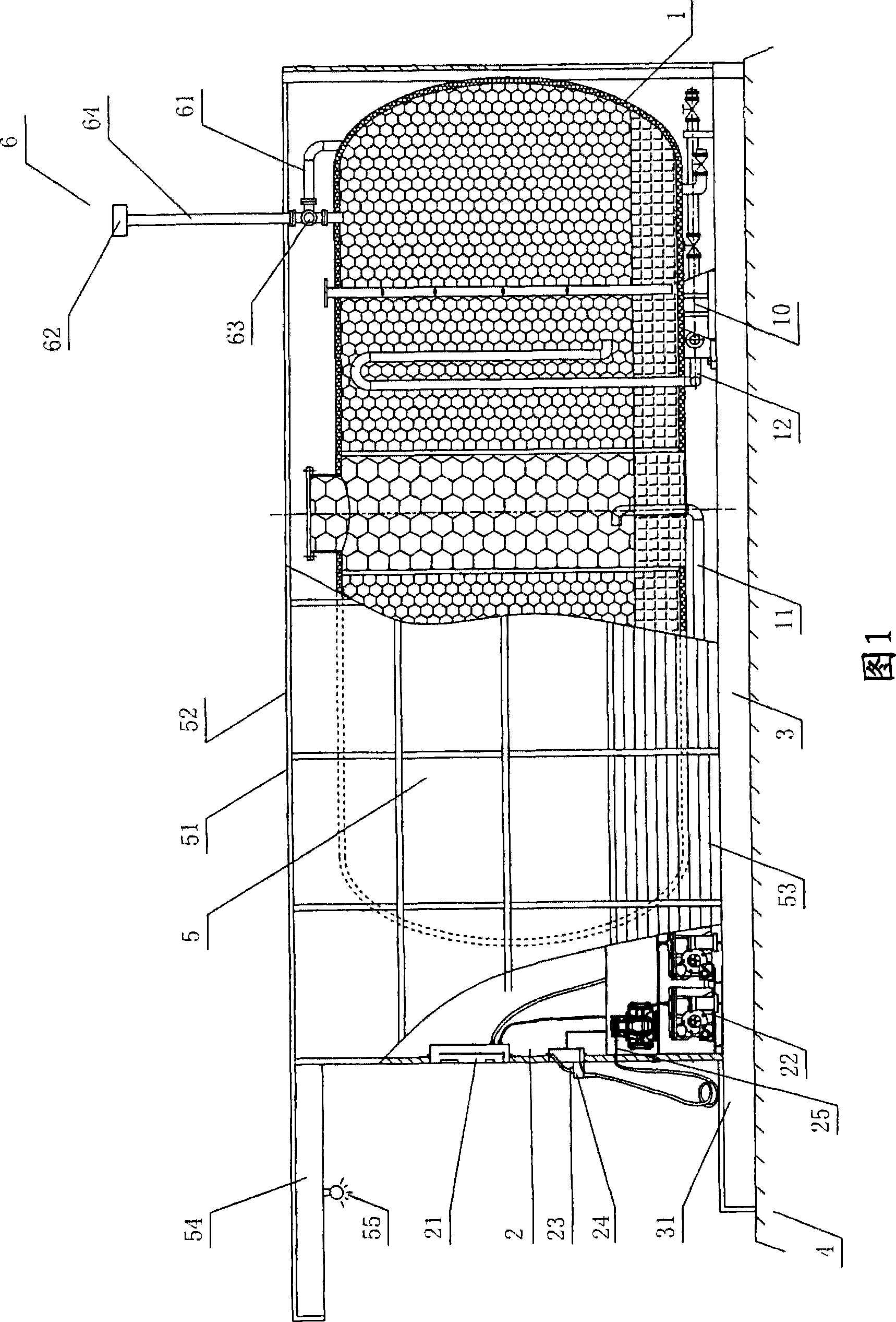
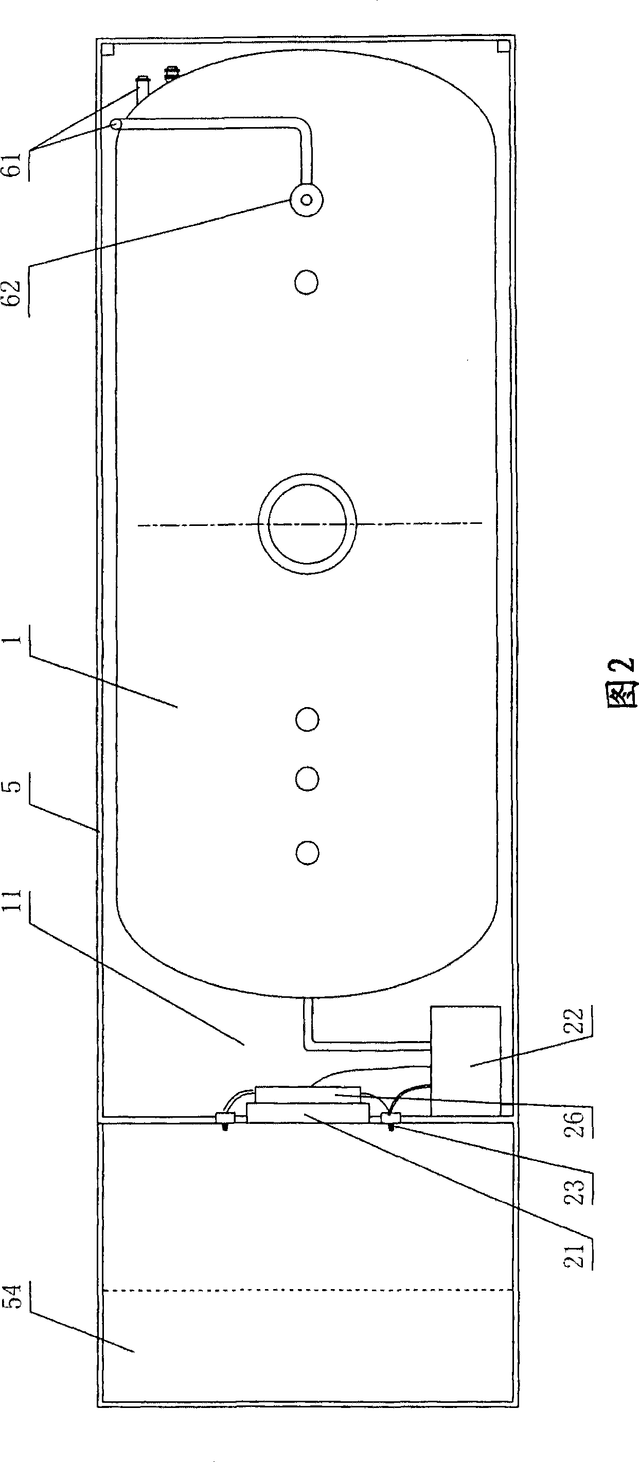
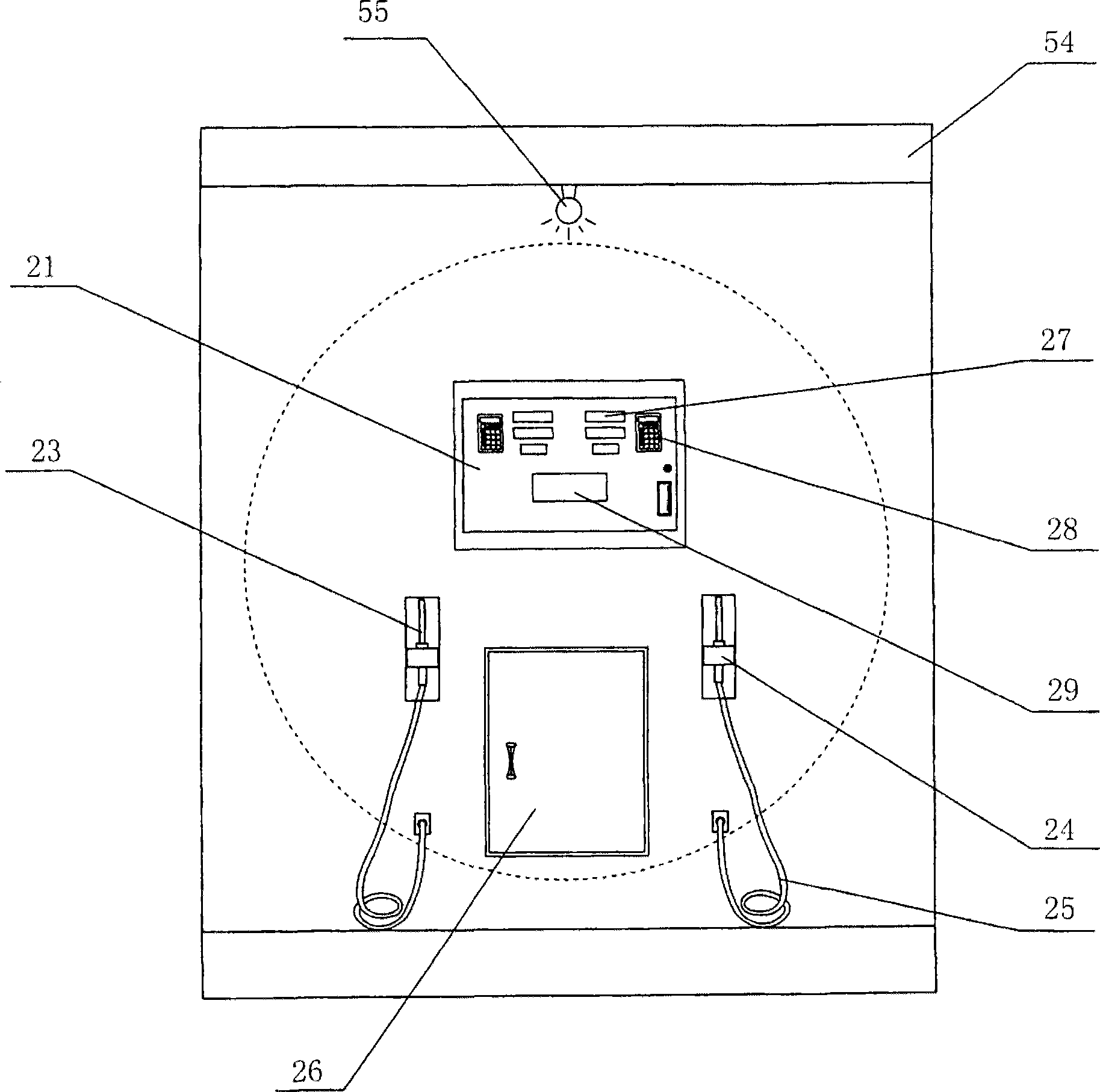
[0031] As shown in Figure 1, it is a schematic diagram of the overall structure of the safe, environment-friendly and energy-saving refueling device of the present invention, and Figure 2 is a top view of Figure 1 of the present invention. It can be seen from FIG. 1 and FIG. 2 that the present invention provides a safe, environment-friendly and energy-saving refueling device, which at least includes an oil storage tank 1 . The oil outlet pipe 11 of the oil storage tank 1 is connected with the fuel dispenser 2, and the bottom of the oil storage tank 1 is provided with a support 10. The formed interlayers are filled with barrier and explosion-proof materials respectively, and a skid body 3 is provided under the oil storage tank 1, and the skid body 3 is fixed on the anti-collision foundation 4 by bolts to form a movable safe, environmentally friendly, and energy-saving refueling device; The body 3 is provided with a cover body 5 . Usually, the skid body 3 is a rectangular frame...


PUM


Abstract

A movable fuel-filling station with a device for recovering fuel-gas airtightly comprises at least a fuel-storing tank, a fuel outlet pipe of which is connected with a fuel-filling machine. The fuel-storing tank is a dual-wall tank. A barrier and antiexplosion material is filled into an inner chamber of the fuel-storing tank and an interlayer composed by the dual layer walls of the tank, respectively. A skid body is disposed below the fuel-storing tank and the fuel-filling machine. A cover is disposed above the skid body. The skid body is fixed to the anticollision ground so as to form a movable fuel-filling station. A fuel-gas recovering device disposed on the fuel-storing tank includes a breather valve disposed on the same tank and a three-way valve mounted on a pipe, which communicates with the fuel-storing tank through the breather valve. One end of the three-way valve is connected with a fuel-gas recovering pipe, a filler neck of which is connected with a joint of a fuel-gas recovering pipe of a tank truck during the filling into the fuel-storing tank. This movable fuel-filling station can greatly reduce floor space, achieve an airtight recover of the fuel-gas, efficiently reduce harm to atmosphere, and save energy.

Description

technical field [0001] The invention relates to a refueling device, in particular to a safe, environment-friendly and energy-saving refueling device, which is movable on the ground and is used for filling gasoline or diesel fuel tanks of automobiles. Background technique [0002] At present, the oil storage tanks of domestic gas stations have been buried underground for a long time. Due to the erosion of the ground, oil and gas leakage or leakage often occur on the tank wall, which has caused serious pollution and damage to the soil around the gas station, especially to the destruction of groundwater resources. is irreparable. At the same time, a considerable part of these buried gas stations are built in cities, and some are also distributed in downtown areas. With the acceleration of urbanization, newly built high-rise buildings and residential areas gradually engulf the surrounding environment of gas stations, resulting in the safety distance of these gas stations not co...

Claims


Application Information

Patent Timeline
Patent Type & Authority Applications(China)
IPC IPC(8): B60S5/02B65D90/30B67D5/04B67D99/00B67D7/04B67D7/32B67D7/78B67D7/84
CPCB60S5/02B67D7/78B65D90/325B67D7/049B65D88/128B67D7/3236B65D90/30B67D7/04
Inventor 黄晓东
Owner SHANGHAI HUAPENG EXPLOSION PROOF TECH
Learn More